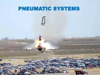
Pneumatic Symbols
Pneumatic Symbols. For system diagrams and component identification. Basic Symbols. Shapes. These shapes and lines in the relative proportions shown, make up a set of basic symbols from which circuits are constructed . Basic Symbols. 2. 12. 10. Working line, pilot supply,

Pneumatic Symbols
E N D
Presentation Transcript
Pneumatic Symbols For system diagrams and component identification
Shapes • These shapes and lines in the relative proportions shown, make up a set of basic symbols from which circuits are constructed
Basic Symbols 2 12 10 Working line, pilot supply, return, electrical Line 3 1 Dashed Pilot control, bleed, filter Chain Enclosure of two or more functions in one unit Line Electrical line
1/4l Functional Elements 1/2l Triangle Direction and nature of fluid, open pneumatic or filled hydraulic Spring size to suit Arrow Long sloping indicates adjustability 1/3l
Functional Elements Arrows Straight or sloping path and flow direction, or motion Tee Closed path or port Restriction Size to suit
Functional Elements Curved arrows rotary motion Shaft rotation clockwise from right hand end anti-clockwise from right hand end both Seating 90o angle
Functional Elements Temperature Indication or control size to suit Operator Opposed solenoid windings M Prime mover Electric motor M
Flowlines Junction Single Junction Four way junction not connected Crossing Hose usually connecting parts with relative movement Flexible line
Connections Air bleed Continuous Temporary by probe Air exhaust No means of connection With means of connection
M Plant • Compressor and electric motor • Air receiver • Isolating valve • Air inlet filter
“l” Actuators • Cylinders symbols can be any length over “l” • The piston and rod can be shown in the retracted, extended or any intermediate position
Single acting • Single acting sprung instroked • Single acting sprung outstroked
Double acting • Double acting adjustable cushions • Double acting through rod
Valve symbol structure • The function of a valve is given by a pair of numerals separated by a stroke, e.g. 3/2.. • The first numeral indicates the number of main ports. These are inlets, outlets and exhausts but excludes signal ports and external pilot feeds. • The second numeral indicates the number of states the valve can achieve.
Valve symbol structure • A 3/2 valve therefore has 3 ports (normally these are inlet, outlet and exhaust) and 2 states (the normal state and the operated state) • The boxes are two pictures of the same valve operated normal
Valve symbol structure • A valve symbol shows the pictures for each of the valve states joined end to end operated normal
Valve symbol structure • A valve symbol shows the pictures for each of the valve states joined end to end operated normal
Valve symbol structure • The port connections are shown to only one of the diagrams to indicate the prevailing state normal
Valve symbol structure • The operator for a particular state is illustrated against that state Operated state produced by pushing a button
Valve symbol structure • The operator for a particular state is illustrated against that state Operated state produced by pushing a button Normal state produced by a spring
Valve symbol structure • The operator for a particular state is illustrated against that state Operated state produced by pushing a button Normal state produced by a spring
Valve symbol structure • The valve symbol can be visualised as moving to align one state or another with the port connections
Valve symbol structure • The valve symbol can be visualised as moving to align one state or another with the port connections
Valve symbol structure • The valve symbol can be visualised as moving to align one state or another with the port connections
Valve symbol structure • A 5/2 valve symbol is constructed in a similar way. A picture of the valve flow paths for each of the two states is shown by the two boxes. The 5 ports are normally an inlet, 2 outlets and 2 exhausts
Valve symbol structure • The full symbol is then made by joining the two boxes and adding operators. The connections are shown against only the prevailing state
Valve symbol structure • The full symbol is then made by joining the two boxes and adding operators. The connections are shown against only the prevailing state
Valve symbol structure • The full symbol is then made by joining the two boxes and adding operators. The connections are shown against only the prevailing state
Valve symbol structure • The boxes can be joined at either end but the operator must be drawn against the state that it produces. The boxes can also be flipped • A variety of symbol patterns are possible normally closed normally open
Valve symbol structure • The boxes can be joined at either end but the operator must be drawn against the state that it produces. The boxes can also be flipped • A variety of symbol patterns can be produced Reverse connected
Valve functions Basic valves before operators are added Examples, push button operated with spring return Operated position Normal position Function 3/2 Function 5/2
Operators Manual General manual Lever Push button Pedal Pull button Treadle Push/pull button Rotary knob
Operators Mechanical Plunger Pressure Spring normally as a return Pilot pressure Roller Differential pressure Uni-direction or one way trip Detent in 3 positions
Operators Electrical Solenoid direct Solenoid pilot with manual override and external pilot supply Solenoid pilot When no integral or external pilot supply is shown it is assumed to be integral Solenoid pilot with manual override and integral pilot supply
2 3 1 Port Markings Push Button 3/2 Valve Spring Return 4 2 Push Button 5/2 Valve Spring Return 1 5 3