LCLS Project Overview
LCLS Project Overview. What is the LCLS ? Transition from 3 rd generation light sources to x-ray free-electron lasers The SASE principle and linac-driven free-electron lasers Performance Accomplishments R&D and construction plan. What is the LCLS ?. Single pass Free-Electron Lasers

LCLS Project Overview
E N D
Presentation Transcript
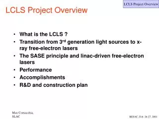
LCLS Project Overview • What is the LCLS ? • Transition from 3rd generation light sources to x-ray free-electron lasers • The SASE principle and linac-driven free-electron lasers • Performance • Accomplishments • R&D and construction plan
What is the LCLS ? • Single pass Free-Electron Lasers • Uses SLAC Linac • 1.5 - 15 Å (0.5-5 Å in 3rd harmonic) • Peak brightness 10 orders of magnitude above Advanced Photon Source (APS) • Time averaged brightness 2-4 orders of magnitude above APS • Sub-picosecond pulses • Fully transversely coherent radiation • Design and R&D studies, a ANL-BNL-LANL-LLNL-SLAC-UCLA collaboration • The X-ray FEL is a powerful tool to explore matter and fundamental physics.
The transition from 3rd generation light sources to x-ray free-electron lasers FELs
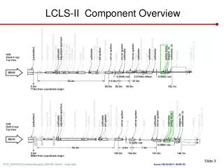
Main components of a SASE FEL A bright electron source (photo-injector) A bunch compression system A linear accelerator An undulator The photon beamlines The experimental areas The SASE principle and linac-driven free-electron lasers
SASE FELs SASE FEL theory well developed and verified by simulations and experiments • FEL radiation starts from noise in spontaneous radiation • Transverse radiation electric field modulates the energy and bunches the electrons within an optical wavelength • Exponential build-up of radiation along undulator length Saturation Exponential Gain Regime Undulator Regime 0.9 fs 1 % of X-Ray Pulse 0.2 fs Electron BunchMicro-Bunching
Wavelength 1.5 Å (range 1.5-15 Å, 1st harm) Electron energy 14.35 GeV (range 14.35-4.54) Bunch length 230 fsec (full) 1012 coherent photons/pulse Undulator length 120 m Undulator gap 6 mm Saturation peak power 9 GW Peak brightness 1.2 1033 Average brightness 4.2 1022 Main parameters
Light source performance chart Average Peak Peak and time averaged brightness of the LCLS and other facilities, operating or planned
Other FEL based light sources are being tested, built or planned • The TESLA Test Facility (TTF) at DESY • Lasing with gain ~3000 observed at 80-180 nm • X-ray FEL TESLA at DESY (associated with the linear collider project) • CDR being written • Source Development Laboratory (SDL) at BNL-NSLS • Electron beam testing • Harmonic Generation (HGHG) experiment successful at BNL-ATF • VISA experiment at BNL-ATF • Study the FEL radiation with beam characteristics and tolerances close to those of the LCLS • FELs under study in Japan, Italy, England and Germany (BESSY II) • LEUTL at ANL-APS • First observation of saturation
FEL experiment • A crucial milestone in FEL physics was reached when the LEUTL experiment measured large amplification and evidence of saturation last summer at 530 and 385 nm
6D particle tracking through LCLS accelerator 150 MeV 250 MeV Energy deviation along electron bunch Transverse cross section of electron beam 250 MeV 4.54 GeV 14.3 GeV
How to achieve a short bunch • The simulation tool was used to optimize the electron beam in 6-dimensional phase space • Preservation of transverse electron brightness leads to shorter undulator and more relaxed tolerances • Mechanism for achieving short electron bunches (230 fs) confirmed by the simulations • Even shorter bunches can compromise transverse electron brightness 230 fs bunch length is the result of optimization in all 6 dimensions
watts c m2 watts c m2 watts c m2 watts c m2 x 1015 x 1017 x 1017 x 1015 Power Density Time Domain Frequency Domain Power Density 1.94 Temporal Transform 1.73 0 0 w0-400/fs w0 w0+400/fs 2 4 0 6 Time, femtoseconds frequency 0 150 Spatial Transform Power Density Power Density 1.94 1.73 0 0 -325 -10 304 -150 0 150 Wavenumber, mm-1 Transverse position, microns X-ray optics transport simulations Viewer GINGER output: Tables of electric field values at undulator exit at different times viewer R, mm Transformation to Frequency Domain Propagation to arbitrary z
LCLS Undulator Hall and Experimental Area Layout FFTB hall for undulator and diagnostics Hall A: Atomic Physics Warm Dense Matter X-Ray Physics Hall B: Nanoscale Dynamics Femtochemistry Biological Imaging
Conceptual Design Report • Conceptual Design Report is on schedule • First draft contributions are being reviewed • Goal is to have it ready, in draft form, by early summer 2001
Summary • Substantial progress made in most areas • Experimental confirmation of the photo-injector brightness is the most important short term goal • Program is receiving strong support from SLAC • Integration photo-injector/FEL physics/x-ray optics to continue • Realistic x-ray FEL characteristics, tolerances, match to the experiments • X-ray optics to address detailed requirements of the “first experiments” • Focus on CDR for the next 6-8 months • Preparation for Lehman Review