ENGINEERING GRAPHICS 1E7
ENGINEERING GRAPHICS 1E7. Lecture 8: Perspective. Pictorial drawings .

ENGINEERING GRAPHICS 1E7
E N D
Presentation Transcript
ENGINEERING GRAPHICS1E7 Lecture 8: Perspective
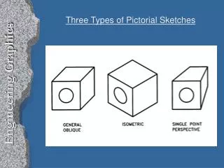
Pictorial drawings Perspective drawings differ from other types of pictorial drawings. In Isometric, Dimetric, and Trimetric drawings, remain parallel and never converge at a single point. They are useful for conveying technical information but lack the quality of realism when compared to the perspective view.
Perspective System MAIN ELEMENTS • The observer’s eye • The object • The plane of projection • Line of sights
Observer’s Eye • Observer’s eye is station point SP • Visual ray at eye level marks horizon on picture plane • The central line of sight should direct towards the centre of interest. • For small or medium-sized objects, place SP slightly above the object, For large objects, place the station point at eye level • The station point is the most influential element of perspective drawing because it affects location, viewpoint, and perspective.
The Object • The position of the object changes the perspective
Plane of Projection & Projector • The picture plane (PP) is the imaginary vertical plane placed between the eye of the observer and the object being drawn. • The location of the plane of projection determines the size of the object on the PP. Moving the PP alters perspective or scale but not proportion. • A picture plane, plane of projection, and drawing surface may be the same • Projectors are imaginary lines from the observer’s eye to the object being drawn. The range of view of visual rays/projectors is called the cone of vision
Vanishing Point Etc. • The lines parallel to each other but not parallel to the PP (horizontal lines) converge towards a single point on the horizon - Vanishing points (VP) • VP is also known as the centre of vision (CV). • The horizon line (HL) is the position of horizon. HL is also known as the eye level. • The ground line (GL) represents the edge of ground plane on which object rests. GL defines the lower limit of drawing.
1-point perspective drawing (1) A simple one-point perspective of a cube is to be constructed from a plan view Step 1Establish an arbitrary horizon line (HL) depending on the eye level you wish to portray Step 2 Locate the picture plane (PP) so that it does not interfere with the drawing. (The PP may be same as HL)
1-point perspective drawing(2) Step 3 Draw the plan view above or below the PP (easier to draw it resting on top of PP)
1-point perspective drawing(3) Step 4Draw the ground line (GL) in an arbitrary location below and parallel to the PP
1-point perspective drawing(4) Step 5Locate the station point (SP) not less than twice the width of the object and directly in front of or to one side of the plan view. (SP may also be placed 2 or 3 times the object’s greatest length from the nearest point of the plan view but if placed any closer, distortion of the perspective will result.)
1-point perspective drawing(5) Step 6 Project the width of the plan view to the GL. Step 7Draw the elevation of the object on GL. If the plan view of the object is touching the PP, the elevation is true in size. If the plan view is behind or in front of PP, the elevation is smaller or larger, respectively Step 8 Project a vertical line from the SP to the HL to locate the VP
1-point perspective drawing(6) Step 9From the corners of the front view (D, E, G and F), draw visual rays to VP
1-point perspective drawing(7) Step 10 The line from point A of the plan view to SP intersects the PP at point H. Draw a perpendicular line from H to intersect the visual rays (points J and K).
(Recap) 1-pt. Perspective The measurement of height has to be taken from the front view or the end view as the plan view only gives information about length and width.
1-point perspective of circle (1) Curves and circles in perspective appear in true shape and size when the surface containing the curve or circle is parallel to PP. Otherwise curves and circles appear as ellipses. Ellipses have no direct transferable measurement; therefore you must place the circle within a square. By inscribing the circle within a square, the vanishing points and proportions of the curves are easily determined.
1-point perspective of circle (2) • Draw a circle with the dimensions desired. • Draw a square circumscribing the circle. Construct centre lines and diagonals inside the square. The intersections of the circle, the centre lines, and the diagonals give eight checkpoints for drawing the circle in perspective . • Draw the square in one-point perspective including the centre lines and diagonals. • Draw in the circle through the eight checkpoints using French curves.