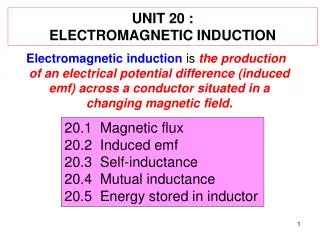
UNIT 20 : ELECTROMAGNETIC INDUCTION
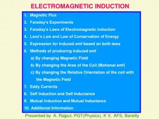
UNIT 20 : ELECTROMAGNETIC INDUCTION. Electromagnetic induction is the production of an electrical potential difference (induced emf) across a conductor situated in a changing magnetic field. 20.1 Magnetic flux 20.2 Induced emf 20.3 Self-inductance 20.4 Mutual inductance

UNIT 20 : ELECTROMAGNETIC INDUCTION
E N D
Presentation Transcript
UNIT 20 : ELECTROMAGNETIC INDUCTION Electromagnetic induction is the production of an electrical potential difference (induced emf) across a conductor situated in a changing magnetic field. 20.1 Magnetic flux 20.2 Induced emf 20.3 Self-inductance 20.4 Mutual inductance 20.5 Energy stored in inductor
area, A 20.1 MAGNETIC FLUX ,Φ • is defined as the scalar product between • the magnetic flux density, B and the vector • of the surface area, A. Unit:T.m2 or Wb = 90 = 0
Example 20.1.1 • A small surface of area 10 mm2 inside a uniform magnetic field of strength 0.10 T is inclined at an angle α to the direction of the field. Determine the magnetic flux through the surface if • α = 0º, • α = 30º • α = 90º Solution :
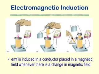
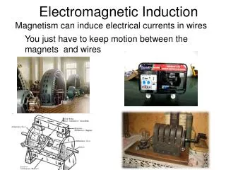
20.2 INDUCED EMF • An electric current produces a magnetic field. • (chapter 19) If electric currents produce a magnetic field, is it possible that a magnetic field can produce an electric current ? • Scientists (American Joseph Henry and the • Englishman Michael Faraday) independently • found that is possible. • Henry actually made the discovery first, but • Faraday published his results earlier and • investigated the subject in more detail.
20.2 INDUCED EMF • The diagram below shows the apparatus used • by Faraday in his attempt to produce an • electric current from a magnetic field. Faraday’s experiment to induce an emf
20.2 INDUCED EMF • In this experiment, Faraday hoped by using a • strong enough battery, a steady current in X • would produce a current in a second coil Y but • failed. • Faraday saw the galvanometer in circuit Y • deflect strongly at the moment he closed the • switch in circuit X. • And the galvanometer deflected strongly in • the opposite direction when he opened the • switch. • A steady current in X had produced no • current in Y.
20.2 INDUCED EMF • Only when the current in X was starting or • stopping was a current produced in Y. • Faraday concluded that although a steady • magnetic field produces no current, a • changing magnetic field can produce an • electric current. • Such a current is called an induced current. • We therefore say that an induced current is • produced by a changing magnetic field. • The corresponding emf required to cause • this current is called an induced emf.
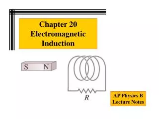
20.2 INDUCED EMF • Induced emf is an electromotive force • resulting from the motion of a conductor • through a magnetic field , or from a change in • the magnetic flux that threads a conductor. • Faraday did further experiments on electromagnetic induction, as this phenomenon is called.( refer diagram ) • A current is induced when a magnet is • moved toward a coil/loop. b) The induced current is opposite when the magnet is moved away from the coil/loop. c) No current is induced if the magnet does not move relative to the coil/loop.
20.2 INDUCED EMF Micheal Faraday’s experiment
20.2 INDUCED EMF Micheal Faraday’s experiment
20.2 INDUCED EMF • Direction of the induced current depends on : • i ) the direction of the magnet’s motion and • ii) the direction of the magnetic field. • Magnitude of the induced current depends on : • i ) the speed of motion (v↑,Iind↑) • ii) the number of turns of the coil (N↑,Iind↑) • iii)the strength of the magnetic field (B↑,Iind↑) • From the observations, Michael Faraday • found that, “ the current/emf is induced in a coil/loop or complete circuit whenever there is a change in the magnetic flux through the area surrounded by the coil”
20.2 INDUCED EMF Faraday’s law and Lenz’s law Faraday’s law “the magnitude of the induced e.m.f. is proportional to the rate of change of the magnetic flux” Lenz’s law “an induced electric current always flows in such a direction that it opposes the change producing it.”
20.2 INDUCED EMF Faraday’s law and Lenz’s law • These two laws are summed up in the • relationship, or The (-) sign indicates that the direction of induced e.m.f. always opposes the change of magnetic flux producing it (Lenz’s law).
20.2 INDUCED EMF Faraday’s law and Lenz’s law • The concept of Faraday's Law is that any change • in the magnetic environment of a coil of wire will • cause a voltage (emf) to be "induced" in the coil. • No matter how the change is produced, the • voltage will be generated. • The change could be produced by • a) changing the magnetic field strength, • b) moving a magnet toward or away from the • coil, • c) moving the coil into or out of the magnetic • field, • d) rotating the coil relative to the magnet, etc.
(A) Induced emf in coil 20.2 INDUCED EMF Faraday’s law and Lenz’s law
(A) Induced emf in coil 20.2 INDUCED EMF Faraday’s law and Lenz’s law Notes i ) the magnitude of induced emf, ii) the flux through the coil can change in any of 3 ways, a) B , b) A , c)θ
(A) Induced emf in coil 20.2 INDUCED EMF Faraday’s law and Lenz’s law Notes iii) If the coil is connected in series to a resistor of resistance R and the induced e.m.f exist in the coil as shown in figure below. and - +
Lenz's Law (based on censervation of energy) • When an emf is generated by a change in magnetic flux according to Faraday's Law, the polarity of the induced emf (next slide) is such that it produces a current whose magnetic field opposes the change which produces it. • The induced magnetic field inside any loop of wire always acts to keep the magnetic flux in the loop constant. • In the examples below, if the B field is increasing, the induced field acts in opposition to it. • If it is decreasing, the induced field acts in the direction of the applied field to try to keep it constant.
(A) Induced emf in coil 7.2 INDUCED EMF Faraday’s law and Lenz’s law The polarity of the induced emf Induced current is directed out of the positive terminal, through the attached device (resistance) and into the negative terminal.
(A) Induced emf in coil Faraday’s law and Lenz’s law Example 20.2.1 A coil of wire 8 cm in diameter has 50 turns and is placed in a B field of 1.8 T. If the B field is reduced to 0.6 T in 0.002 s , calculate the induced emf.
Solution Faraday’s law and Lenz’s law d = 8 cm, N = 50 turns, B from 1.8 T to 0.6 T in 0.002 s
(A) Induced emf in coil Faraday’s law and Lenz’s law Example 20.2.2 An elastic circular loop in the plane of the paper lies in a 0.75 T magnetic field pointing into the paper. If the loop’s diamater changes from 20.0 cm to 6.0 cm in 0.50 s, • What is the direction of the induced current, • What is the magnitude of the average induced emf, and • If the loop’s resistance is 2.5 Ω, what is the average induced current during the 0.50 s ?
Faraday’s law and Lenz’s law Solution: B=0.75 T, di= 20.0 cm, df= 6.0 cm, t = 0.50 s • Direction of the induced current, • b) Magnitude of the average induced emf, c) R = 2.5 Ω,
Example 20.2.3 Faraday’s law and Lenz’s law A circular shaped coil 3.05 cm in radius, containing 40 turns and have a resistance of 3.55 is placed perpendicular to a magnetic field of flux density of 1.25 x 10⁻² T. If the magnetic flux density is increased to 0.450 T in time of 0.250 s, calculate the induced current flows in the coil.
(A) Induced emf in coil + - Faraday’s law and Lenz’s law How to determine the direction of induced current.- Lenz’s law Case A Thumb – induced magnetic field Fingers - induced current N Direction of induced current – induced-current right hand rule.
Faraday’s law and Lenz’s law How to determine the direction of induced current.- Lenz’s law Case A • Consider a bar magnet that is moved • towards a solenoid. • As the north pole of the magnet approaches • the solenoid, the amount of magnetic field • passing through the solenoid increases , • thus increasing the magnetic flux through • the solenoid. • The increasing flux induces an emf • (current) in the solenoid and galvanometer • indicates that a current is flowing.
Faraday’s law and Lenz’s law How to determine the direction of induced current.- Lenz’s law Case A • The direction of the induced current is • such as to generate a magnetic field in the • direction that opposes the change in the • magnetic flux, so the direction of the • induced field must be in the direction that • make the solenoid right end becomes a • north pole. • This opposes the motion of the bar magnet • and obey the Lenz’s law.
Faraday’s law and Lenz’s law How to determine the direction of induced current.- Lenz’s law Case B • When the magnet is moved toward the stationary • conducting loop, a current is induced in the • direction shown. (b) This induced current produces its own magnetic field(Binduced) directed to the left that counteracts the increasing external flux. Binduced Bexternal
Faraday’s law and Lenz’s law How to determine the direction of induced current.- Lenz’s law Case B (c) When the magnet is moved away from the stationary conducting loop, a current is induced in the direction shown. (d) This induced current produces a magnetic field (Binduced) directed to the right and so counteracts the decreasing external flux. Binduced Bexternal
(A) Induced emf in coil Faraday’s law and Lenz’s law Faraday’s law and Lenz’s law Example 20.2.4 Calculate the current through a 37 Ω resistor connected to a single turn circular loop 10 cm in diameter, assuming that the magnetic field through the loop is increasing at a rate of 0.050 T/s. State the direction of the current.
Faraday’s law and Lenz’s law Example 20.2.4 R = 37 Ω , d = 10 cm dB/dt = 0.050 T/s. I induced S N I induced Direction of Iinduced : from b to a.
(B) Induced emf of a straight conductor • Consider a straight conductor of length l is moved at a speed v to the right on a U-shaped conductor in a uniform magnetic field B that points out the paper. • This conductor travels a distance dx =vdt in a time dt.
(B) Induced emf of a straight conductor • The area of the loop increases by an amount • According to Faraday’s law, the e.m.f. is induced in the conductor and its magnitude is given by
(B) Induced emf of a straight conductor θ = angle between v and B = 90 o • This induced emf is called motional induced emf.
(B) Induced emf of a straight conductor • As the conductor is moved to the right (Fapplied to the right) with speed v, the magnetic flux through the loop increases. • A current is induced in the loop. • The induced current flows in the direction that tends to oppose this change. FB Fapplied • In order to oppose this change, the current through the conductor must produce a magnetic force (F=BIL) directed to the left.
(B)Induced emf of a straight conductor Faraday’s law and Lenz’s law • The direction of the induced current due to induced e.m.f. flows in the linear conductor can be determine by using Fleming’s right hand rule (based on lenz’s law). • The induced current flows from P to Q. P FB Fapplied Fapplied Q Thumb – direction of Motion First finger – direction of Field Second finger – direction of Induced current or Induced e.m.f. Only for the straight conductor.
Polarity (B)Induced emf of a straight conductor • When the conductor is moved to the right (Fapplied to the right) with speed v, the electrons in the rod move with the same speed. • Therefore, each feels a force F=Bqv, which acts upward in the figure. • If the rod were not in contact with the U-shaped conductor, electrons would collect at the upper end of the rod, leaving the lower end positive. There must thus be an induced emf.
Example 20.2.5 Induced emf of a straight conductor Suppose the length in figure above is 0.10 m, the velocity z is 2.5 m/s, the total resistance of the loop is 0.030 Ω and B is 0.60 T. Calculate a) the induced emf b) the induced current c) the force acting on the rod d) the power dissipated in the loop
Example 20.2.6 Induced emf of a straight conductor A 0.2-m length of wire moves at a constant velocity of 4 m/s in a direction that is 40 o with respect to a magnetic flux density of 0.5 T. Calculate the induced emf.
Example 20.2.7 Induced emf of a straight conductor In figure above, a rod with length l = 0.400 m moves in a magnetic flux with magnitude B = 1.20 T. The emf induced in the moving rod is 3.60 V. • Calculate the speed of the rod. • If the total resistance is 0.900 Ω, • calculate the induced current. • What force does the field exert on the • rod as a result of this current? 7.50 m/s , 4.00 A , 1.92 N to the left
(C) Induced emf in a rotating coil An ac generator / dynamo (transforms mechanical energy into electric energy)
(C) Induced emf in a rotating coil An ac generator / dynamo (transforms mechanical energy into electric energy)
(C) Induced emf in a rotating coil • Consider a coil of N turns each of area A and is being rotated about a horizontal axis in its own plane at right angle to a uniform magnetic field of flux density B. • As the coil rotates with the angular speed ω, the orientation of the loop changes with time.
(C) Induced emf in a rotating coil • The emf induced in the loop is given by Faraday’s law, • The emf induced in the loop varies sinusoidally in time.
(C) Induced emf in a rotating coil The alternating emf induced in the loop plotted as a function of time.
Example 20.2.8 Induced emf in a rotating coil The armature of a simple ac generator consists of 100 turns of wire, each having an area of 0.2 m2 . The armature is turned with a frequency of 60 rev/s in a constant magnetic field of flux density 10-3 T. Calculate the maximum emf generated.
28 V 0.42 s 0.21 s 0.63 s 0.84 s -28 V Example 20.2.9 Induced emf in a rotating coil • The drawing shows a plot of the output emf of a generator as a function of time t. The coil of this device has a cross-sectional area per turn of 0.020 m2 and contains 150 turns. Calculate • The frequency of the generator in hertz. • The angular speed in rad/s • The magnitude of the magnetic field. 2.4 Hz , 15 rad/s , 0.62 T
Example 20.2.10 Induced emf in a rotating coil An amarture in ac generator consists of 500 turns, each of area 60 cm2 . The amarture is rotated at a frequency of 3600 rpm in a uniform 2 mT magnetic field. Calculate a) the frequency of the alternating emf b) the maximum emf generated c) the instantaneous emf at time when the plane of the coil makes an angle of 60o with the magnetic field ? 380 rad/s, 1.13 V, 2.26 V