Download
1 / 15
150 likes | 257 Vues
Helga Timk ó. Plasma-Wall Interactions – Part I I : In Linear Collider s. Department of Physics University of Helsinki Finland. Plasma-Wall Interactions – Outline. Part I: In Fusion Reactors Materials Science Aspect Materials for Plasma Facing Components Beryllium Simulations

E N D
Helga Timkó Plasma-Wall Interactions – Part II: In LinearColliders Department of Physics University of Helsinki Finland
Plasma-Wall Interactions – Outline • Part I: In Fusion Reactors • Materials Science Aspect • Materials for Plasma Facing Components • Beryllium Simulations • Arcing in Fusion Reactors • Part II: In Linear Colliders • Arcing in CLIC Accelerating Components • Particle-in-Cell Simulations • Future Plans for a Multi-scale Model
Last Week:Arcing in Fusion Reactors Arcing = continuous gas discharge, between electrodes or within the plasma sheath Causes in fusion reactors Erosion, Impurities And thus, plasma instabilities harder to reach confinement Research on arcing has been done since 1970’s Search for arc-resistant materials, ideal surface conditions Theoretical and experimental modelling of arcing in simplified geometries All in all, in fusion reactors arcing not so critical any more But for future linear colliders it is!
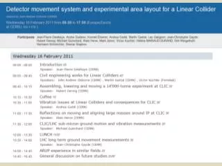
CLIC = Compact Linear Collider‘only’ 47.9 km • A proposed e- – e+ linear collider, with a CM energy of up to 3 TeV in the final design (cf. LEP max. 209 GeV) • Linear colliders more effective than circular ones • Can reach higher energies • With CLIC, post-LHC physics can be done, e.g. for Higgs physics this means: • LHC should see Higgs(es), should rule out some theories • CLIC would be able to measure particle properties • To be built in three steps • Two-beam acceleration
CLIC accelerating components • Under testing in the CTF3 project at CERN • Too high breakdown rates, 10-4, aim: 10-7 for final design • Different setups have been tested: • Geometries • Materials: Cu and Mo best • Frequencies: main linac fRF was lowered 30 → 12 GHz • Most challenging is the high accelerating gradient to be achieved, already lowered too 150 → 100 MV/m • Need: a theoretical model of breakdown to systemise
What is PIC and what can we simulate with it? • PIC = Particle-in-Cell method • Basic idea: simulate the time evolution of macro quantities instead of particle position and velocity (cf. MD method) • Need superparticles • Restricted to certain regime of particle density given by reference values (those define dimensionless quantities) • Kinetic approach of plasma, but can be applied both for collisionless and collisional plasmas • Many application fields: solid state and quantum physics as well as in fluid mechnics • Has become very popular in plasma physical applications • Esp. for modelling fusion reactor plasmas (sheath and edge)
The PIC Algorithm • Setting up the simulation: • Grid size, timestep, superparticles, scaling • Solving the equations of motion » particle mover « • Moving particles, taking collisions & BC’s into account • Calculating plasma parameters, macro quatities • Solving Maxwell’s equations, (Poisson’s eq. in our case) • this can be done with different » solvers « • Obtaining fields and forces at grid points • In PIC, everything is calculated on the grid, interpolation to particle positions is done by the » weighting scheme «
Solvers forthe Particle Mover and the Poisson’s Equation • Discretised equations of motion: • In 1D el.stat. case, with the leapfrog method, in the Boris scheme: • Poisson’s equation determining the electric field from charge density values at grid points:
Scaling in PIC – Grid size and timestep • In the code, everything is scaled to dimensionless quantities → easier to analyse physically, faster code • Initial values give the scale for the simulations, only a few orders of magnitudes can be captured • Need a good guess: n0 = 1018 cm-3, Te = 5 keV • Determines λD = 5.3×10⁻⁷ m and ωpe = 5.6×10¹³ 1/s, the internal units of the code • For an arc, densities are only rising! model is limited • Stability conditions: • Compromise btw. efficiency and low noise: Δx = 0.5 λD, Δt = 0.2× 1/ωpe • Amazing: whole set of equations can be rescaled universal results; only the incl. of collisions gives a scale
Our Model • In collaboration with the Max-Planck-Institut f. Plasmaphysik, Greifswald • 1D electrostatic, collision dominated PIC scheme • Simplistic surface interaction model: • Assuming const. electron thermoemission current (cathode) • Const. flux of evaporated neutral Cu atoms, Icu=0.01Ith,e • Cu+ ions sputter Cu with 100% probab., neutral Cu is reflected back when hitting the walls
Including collisions • Arcing highly collision dominated, so is our model • Including only 3 species: electrons, neutral Cu, Cu+ ions • Multiply ionised species ignored • Most important collisions are taken into account:
A Typical Output • Macro quantities as a function of time • Flux and energy distributions, currents • Note the sheath! Animations by K. Matyash:
The Plasma Sheath • Sheath = a thin layer of a few Debyes near the wall • All physics happens in the sheath: • Field & density gradients, collisions • Outside, the potential is constant, field is zero: Doesn’t really matter what the dimensions of the system are (nm or μm)
Future plans: Integrated Modelling of Arcing MPI Greifswald K. Matyash R. Schneider HIP, Helsinki H. Timko F. Djurabekova K. Nordlund • Multi-scale model aimed: an integrated PIC & MD model of arcing • Collaboration between: • Max-Planck-Institut für Plasmaphysik • Helsinki Institute of Physics
Thank You! Bibliography: D. Tskhakaya, K. Matyash, R. Schneider and F. Taccogna: The Particle-In-Cell Method, Contributions to Plasma Physics 47 (2007) 563. Computational Many-Particle Physics,Springer Verlag, Series: Lecture Notes in Physics, Vol. 739 (2008) Editors: H. Fehske, R. Schneider and A. Weiße Information: http://clic-study.web.cern.ch/clic-study/ http://beam.acclab.helsinki.fi/~knordlun/arcmd/