Download
1 / 41
410 likes | 462 Vues
Learn about common techniques, potential artifacts, and safety precautions in preparing TEM specimens. Gain practical skills for choosing the right technique for your sample. Safety measures, polishing solutions, and considerations before preparation are discussed in detail. Understand the objective of TEM work, various preparation philosophies, and methods like cutting, grinding, dimpling, and coating. Detailed instructions on preparing self-supporting discs, grids, washers, and thinning techniques are provided to help you master the art of specimen preparation for TEM analysis.

E N D
Sample ??? Specimen preparation Basedonchapter 10 in TEM by Williams and Carter, 2009
Learning outcome • HMS awareness • Overview of common techniques • Possible artifacts • You should be able to evaluate which technique to use for a given sample • Lab will give you some practical skills
SAFETY!!!! • Know what you handling. • MSDS • Protect your self and others around you. • Follow instructions • If an accident occurs, know how to respond. Polishing solutions: Hydrogen cyanide, hydrofluoric acid, nitric acid, and perchloric acid!!
Work in the Stucture Physics lab • Get the local HMS instructions from Ole Bjørn Karlsen Sign a form confirming that you have got the information Ask
Safety rules • Be sure that you can safely dispose of the waste product before you start. • Be sure you have the ‘antidote’ at hand. • Never work alone in the specimen-preparation laboratory. • Always wear safety glasses when preparing specimens and/or full protective clothing, including face masks and gloves, if so advised by the safety manual. • Only make up enough of the solution for the one polishing session. Never use a mouth pipette for measuring any component of the solution. Dispose of the solution after use. • Always work in a fume hood when using chemicals. • Check that the extraction rate of the hood is sufficient for thechemical used.
Someacids for specimenpreparation • Cyanide solutions: • DO NOT USE • Perchloric acid in ethanol or methanol • Ole Bjørn will make the solution if needed • Nitric acid (HNO3 ) • Can produce explosive mixtures with ethanol. • Hydrofluoric acid (HF) • Penetrates flesh and dissolves bones rapidly! You need to have approval by supervisors and Ole Bjørn first!
What to considder before preparing a TEM specimen • Ductile/fragile • Bulk/surface/powder • Insulating/conducting • Heat resistant • Irradiation resistant • Single phase/multi phase • Can mechanical damage be tolerated? • Can chemical changes be accepted? • Etc, etc……. What is the objectiv of the TEM work? Examples:
Preparation philosofies Self-supportingdiscs or specimensupportedon a grid or washer
Self-supporting disk or grid • Self supporting disk • Consists of one material • Can be a composite • Can be handled with a tweeser • Metallic, magnetic, non-magnetic, plastic, vacuum If brittle, consider Cu washer with a slot • Grid and washer • Several types • Different materials (Cu, Ni…) • Support brittle materials • Support small particles
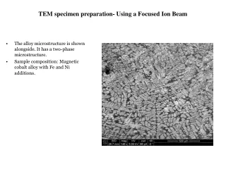
Grids and washers used as specimen support May contribute to the EDS signal. Common size: 3 mm. Smaller specimen diameters can be used for certain holders.
Crushing Cutting saw, “diamond” pen, ultrasonic drill, FIB Mechanical thinning Grinding, dimpling, Tripod polishing Electrochemical thinning Ion milling Coating Replica methods FIB Etc. Specimen preparation for TEM
Preparation of self-supporting discs • Cutting/cleaving • Ductile material or not?
Cutting and cleaving • Si • GaAs • NaCl • MgO Cutting with a saw: Soft or brittle material? Brittle materials with well-defined cleavage plane Razor blade or ultramicrotome
Preparation of self-supporting discs • Cutting/cleaving • Ductile material or not? • Grinding • 100-200 μm thick • polish • Cut the 3mm disc
Cutting a 3 mm disc Soft or brittle material? Mechanical damage OK? Brittle: Spark erosion, ultrasonic drill, grinding drill
Preparation of self-supporting discs • Cutting • Ductile material or not? • Grinding • 100-200 μm thick • polish • Cut the 3mm disc • Prethinning • Dimpling • Tripod polishing
Dimpling F ΔΖ ω
Surface dimpling using a chemical solution Si: HF + HNO3 GaAs: Br + methanol The light pipe permits visual detection of perforation using the mirror.
Preparation of self-supporting discs • Cutting • Ductile material or not? • Grinding • 100-200 μm thick • polish • Cut the 3mm disc • Prethinning • Final thinning • Ion beam milling • Electropolishing
Final thinning of the discs • Electropolishing • Ionmilling
Jet polishing A single jet of gravityfed electrolyte thin a disk supported on a positively charged gauze. The disk has to be rotated periodically. Twin-jet electropolishing apparatus. The positively charged specimen is held in a Teflon holder between the jets. A light pipe (not shown) detects perforation and terminates the polishing.
Ar ion beam thinning Variation in penetration depth and thinning rate with the angle of incidence.
Effect of Ar-thinning on CdTe Defects (dark spots) in Ar-thinned specimen Crystal thinned by reactive iodine ion milling.
Preparation philosofies Self-supportingdiscs or specimensupportedon a grid or washer
Preparation of particles and fibers first embedding them in epoxy and forcing the epoxy into a 3-mm (outside) diameter brass tube prior to curing the epoxy. The tube and epoxy are then sectioned into disks with a diamond saw, dimpled, and ion milled to transparency.
Top view Preparation of thin films Grind down/ dimple Cut out cylinder Ione beam thinning Grind down and glue on Cu-rings Cut out a cylinder and glue it in a Cu-tube Cut out slices • Cross section or Glue the interface of interest face to face together with support material • Focused Ion Beam (FIB) Cut a slice of the cylinder and grind it down / dimple Cut off excess material Ione beam thinning
Preparation of thin films Spacers : Si, glass, or some other inexpensive material.
Specimens on grids/washers • Electropolishing • The window method • Ultramicrotomy • Crushing • In ethanol • Mix in an epoxy • Replication and extraction • Cleaving and SACT • The 90o wedge • Lithography • Preferensial chemical etching
. Window polishing A sheet of the metal 100mm2 is lacquered around the edges and made the anode of an electrolytic cell. Progress during thinning: the initial perforation usually occurs at the top of the sheet; lacquer is used to cover the initial perforation and the sheet is rotated 180o and thinning continues to ensure that final thinning occurs near the center of the sheet.
Ultramicrotomy The sample is first embedded in epoxy or some other medium or the whole sample is clamped and moved across a knife edge. The thin flakes float off onto water or an appropriate inert medium, from where they are collected on grids.
Replication of a surface 1) Spray acetone on the surface to be replicated before pressing a plastic (usually cellulose acetate) 2) Removed the plastic from the surface when hardened 3) Evaporate a C, Cr, or Pt film onto the replicated plastic surface. 4) Dissolve the plastic with acetone Alternatively: the direct carbon replica.
Extraction replication The rest of the matrix is etched A thin amorphous carbon film is evaporated over the particles
Cleaving • 1) Use tape • 2) Dissolve tape in a solvent Cleaved MoS2 showing regions of different shades of green, which correspond to different thicknesses.
SACT The small-angle cleaving technique Invaluable for films on Si or glass where there is no crystal structure 1. Scratch the sample; 2. Cleaving along the scratch;
LACT- The 90o wedge • Prethin: 2-mm square of the • multilayers on a Si substrate • 2) Scribe the Si through the surface • layers, turn over, and cleave • Need: a sharp 90o edge; • 3) Mount the 90o corner
Preferential chemical etching Etch away most of the sample, leaving a small etched plateau Mask a region <50 nm across and etch away the majority of the surrounding plateau. Turn 90o and mounted in a specimen holder
Lithographic techniques Etching between the barrier layers Produces an undercutting down to the implanted layer which acts as an etch stop, producing a uniform layer 10 mm thick.
FIB Schematic of a two-beam (electron and ion) FIB instrument. -The area of interest has been marked. -A Pt bar is deposited to protect this area from the Ga beam. -The two trenches are cut. -The bottom and sides of the slice are (final) cut. -The TEM specimen is polished in place before extracting it.
PhD presentations • TEM holders • ETEM holders • FIB • Replica methods • Etching • Plasma cleaning