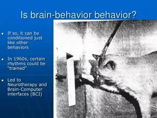
Download
1 / 22
290 likes | 639 Vues
Learn about dielectric materials, polarizability, dielectric loss, complex dielectric constant, and more in AC conditions. Explore the factors affecting power loss, frequency dependence, and examples of dielectric loss in various materials.

E N D
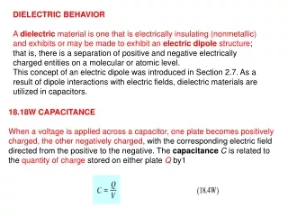
Dielectric Materials • Pre-requisite • Capacitive behavior • Polarization • Dielectric Loss • Insulating behavior • Dielectric Breakdown • Refractive Index • Piezoelectricity & Ferroelectricity
Why is there “dielectric loss” under ac condition Why is “dielectric constant” a complex number “Dielectric loss” and its dependences Complex dielectric constant Equivalent circuit model Dielectric loss and its dependences Some examples of “dielectric loss” in dielectric Dielectric Loss
Input energy from ac voltage through “polarization” process Energy stored in dipoles in dielectric Energy lost as heat Dielectric loss under ac condition So far, the dielectric constant (r) is the static dielectric constant, which is the result of polarization in dielectric under dc conditions If consider dielectric under ac conditions, the dielectric constant is different from the above as energy losses have to be taken into account • Example (orientational polarization): Thermal agitation tries to randomize the dipole orientations dipole moments cannot react instantaneously to changes in the applied field energy loss • Dielectric loss is the electrical energy lost as heat in the polarization process in the presence of an applied ac field. The energy is absorbed from the ac voltage and converted to heat during polarization of the molecules. It should not be confused with conduction loss (V2/R).
Considering dielectric loss (or ac condition), the dielectric constant r is a complex number given by where, r’ is the real part and r’’ is the imaginary part. Complex dielectric constant Under dc condition Under ac condition E-field The lag of “P” over “E” due to energy loss E-field P (polarization) P (polarization) r is a vector, a complex value P=0(r-1)E
Dielectric in ac condition: admittance • Consider parallel plate capacitor with a dielectric • Impedance of the capacitor • Thus, admittance (Y=1/Z) given by
Dielectric in ac condition: equivalent circuit • The admittance can be written in the form • Equivalent circuit: compared to parallel resistance formula. where The admittance of the dielectric medium is equivalent to a parallel combination of an ideal lossless capacitor C’ with a relative permittivity r’ and a resistor with a conductance Gp.
Dielectric loss: loss tangent • Input power: • Real part r’ represents the relative permittivity (static dielectric contribution) in capacitance calculation • imaginary part r’’ represents the energy loss in dielectric medium • Loss tangent: defined as • represents how lossy the material is for ac signals.
Dielectric loss: per unit volume The dielectric loss per unit volume: • Three factors determining power loss per unit volume • Frequency • Electrical field • Loss tangent (or r’’)
Examples of loss tangent of some dielectric materials • Note that the power loss is a function ofω, E and tanδ. • We want a low loss tangent to ensure low power loss for a good electric material. • The loss tangents of some comment dielectrics are listed here.
Frequency dependence of complex dielectric constant • The extent to which the material is polarized is frequency dependent, ie. a is frequency dependent. • Since a and are related, the dielectric constant (both real and imaginary parts) is also frequency dependent. • With each direction reversal, dipoles attempt to re-orient with field. This process requires finite time. For each polarization type, some minimum relaxation time is required, depending on the ease with which the particular dipoles are capable of realignment. A relaxation frequency is taken as the reciprocal of this minimum reorientation time. Dipole cannot keep shifting its orientation direction. When frequency of applied field exceeds the relaxation frequency, the corresponding dipole mechanism will not contribute to r’. • When a polarization mechanism ceases, there is an abrupt drop in r’, otherwise r’ is virtually constant.
Frequency dependence of complex dielectric constant No single well-defined lattice vibration frequency but an allowed range of frequencies (cf allowed range of energies for electrons in solids). • Take the example of ionic polarization. Lattice vibrations occur typically at frequencies = i in the infra-red region. Energy loss (r’’ factor) is greatest when frequency of polarization field equals i as the field will try to randomize the polarization. • Polarization effects depend on crystal orientation. In polycrystalline materials, various peaks overlap to form a broad overall peak. • At low frequencies interfacial polarization or space charge polarization features are even broader since there can be different conduction mechanisms for charges to accumulate at interfaces, each having its own speed.
Dielectric Materials • Pre-requisite • Capacitive behavior • Polarization • Dielectric Loss • Insulating behavior • Dielectric Breakdown • Refractive Index • Piezoelectricity & Ferroelectricity
Insulating behavior: insulating behavior is important as dielectrics are widely used as insulating material media between conductors at different voltages to prevent ionization of air and hence current flashovers between conductors Dielectric breakdown Leakage current (will not cover in detail) Dielectric breakdown: when a voltage is high enough causes a substantial current to flow between the electrodes which appears as a short between two electrodes leads to what so called “dielectric breakdown”. Breakdown occurs at “weak spots” if a substantial current flows when a certain high voltage is reached In liquids and gases, breakdown does not generally damage the material permanently In solids, the breakdown process invariably leads to the formation of a permanent conducting channel and hence permanent damage Define dielectric strength, Ebr, as the maximum field that can be applied without causing dielectric breakdown. Dielectric Breakdown: introduction
Dielectric Breakdown: dielectric strength (Ebr) Dielectric strength (Ebr) is dependent on many factors such as molecular structure, impurities in materials, microstructural defects, sample geometry, nature of electrodes, temperature, ambient conditions, duration and frequency of applied field.
Breakdown in gases: Mechanism: One electron with sufficiently large kinetic energy hits neutral gas molecule (impact ionization) more electrons impact ionize other gas molecules electron avalanche effect. Factors affecting breakdown: Pressure of gas in a critical factor as this represents the mean free path of electron and hence how often the collisions occur. Ebr increases with gas pressure. (Why?) Dielectric Breakdown: in Gases and Liquids • Breakdown in liquids: • - Mechanism is not so clear and can arise from various ways: • Eg 1: In impurity liquids, impurities coalesce end to end to form conducting bridge between electrodes and thereby give rise to discharge; or • Eg 2: In some liquids, the discharge initiates as partial discharge in gas bubbles entrapped in the liquid locally increase temperature and more liquid vaporized size of bubble increased the eventual discharge can be a series of partial discharges in entrapped gas bubbles; • Eg 3: Oxidation of certain liquids (eg. oil) producing more acidic and higher conductivity regions that give rise to discharge.
- Intrinsic or electronic breakdown Free electron in solid accelerated by high field collide and ionize host atom break bond (electron from valence band excited into conduction band) primary and secondary electron further ionize other host atoms electron avalanche breakdown This type of breakdown represents the upper limit that is achievable by ‘perfect’ dielectrics with no defects. - Thermal Breakdown (i) Finite conductivity of dielectric Joule heating in solids (ii) At high frequencies, dielectric loss becomes significant. Conduction and dielectric losses generate heat in material. If heat is not removed rapidly by thermal conduction, then temperature of dielectric rises. (iii) Thermal runaway temperature and current increases until a discharge occurs through various sections of solid. Hot spots which suffer local melting and erosion formed. Dielectric Breakdown: in Solids Many different mechanisms exist in Solid Dielectric Breakdown.
- Electromechanical Breakdown (i) Dielectric medium is situated between oppositely charged plates experiences compressive forces as the two plates attract and pull towards each other (ii) Decrease in dielectric thickness leads to higher field and also more charges on electrode deformation electrofracture dielectric failure Example: polyethylene and polyisobutylene (soft materials) Internal Discharge Partial discharges which occur in microstructural voids, cracks, pores within dielectric where gas atmosphere has lower dielectric strength. Example: In porous ceramics Dielectric Breakdown: in Solids • Insulation Aging • Deterioration with age of insulation or dielectric. • Factors such as irradiation by ionizing radiation (e.g., X-rays), temperature, mechanical stress etc give rise to insulation aging. F F • External Discharges • Surface contamination from external sources such as moisture, pollutants, dirt etc giving sufficient conductance to cause a discharge
Summary of Breakdown field for different mechanisms Typical values of breakdown field for different mechanisms versus time-to-breakdown Different breakdown fields correspond to different time-to-breakdown for different mechanisms. Difficult to isolate breakdown mechanism for a given material.
Dielectric Materials • Pre-requisite • Capacitive behavior • Polarization • Dielectric Loss • Insulating behavior • Dielectric Breakdown • Refractive Index • Piezoelectricity & Ferroelectricity
Refraction is the phenomenon which occurs when light that is transmitted into the interior of a transparent material experiences a change in velocity and is bent at the interface. Electric field (light) interacts with the electron cloud surrounding each atom within its path resulting in electronic polarization. Two consequences of electronic polarization: some of the radiation energy may be absorbed. light waves are retarded in velocity as they pass through the medium, which causes refraction The refractive index of a material, n, is the ratio of the speed of light in vacuum, c, to the speed of light in medium, v, n=c/v Refractive Index
Refractive Index: Relation with dielectric constant at optical frequency • The velocity of light in a medium is related to the dielectric permittivity and the magnetic permeability of the medium. So • Hence refractive index given by • Since most optical materials and dielectrics are only slightly magnetic, we have μr=1, so,
Refractive index n is related to dielectric constant recall electronic polarization in optical frequency range In general, the larger the atom or ion, the greater the electronic polarization the slower the velocity, and the greater the refractive index For cubic crystal structures (e.g., glasses, crystalline ceramics), refractive index is independent of crystallographic direction (i.e., it is isotropic). Non-cubic crystals have an anisotropic n refractive index is greatest along the direction with the highest density of atoms. Refractive Index: Some comments