LOWER BAKER FLOW IMPLEMENTATION DEVELOPMENT OF UNIT 4 POWERHOUSE
180 likes | 353 Vues
LOWER BAKER FLOW IMPLEMENTATION DEVELOPMENT OF UNIT 4 POWERHOUSE. Jeffrey Reichmuth Consulting Engineer. February 18, 2014. TOPICS OF PRESENTATION. 30MW Hydroelectric Facility with Synchronous By-pass Valve and Neighboring 85MW U3 Aquatics Requirements Key to License

LOWER BAKER FLOW IMPLEMENTATION DEVELOPMENT OF UNIT 4 POWERHOUSE
E N D
Presentation Transcript
LOWER BAKER FLOW IMPLEMENTATIONDEVELOPMENT OF UNIT 4 POWERHOUSE Jeffrey Reichmuth Consulting Engineer February 18, 2014
TOPICS OF PRESENTATION • 30MW Hydroelectric Facility with Synchronous By-pass Valve and Neighboring 85MW U3 • Aquatics Requirements Key to License • Minimum In-Stream flow 1200cfs/1000cfs • Ramping Requirements, 1inch per Hour • Control Strategies – Dam, Unit 3, Unit 4, SBV • Economic Dispatch • Construction Started December 2010 • Commissioning June 2013
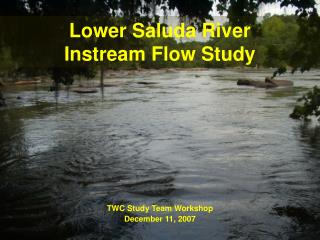
Skagit River Near Concrete Washington Skagit River USGS Gage for In-stream Flow Compliance Baker River USGS Gage - Minimum In-Stream Flow 1200/1000 cfs Ramping Restrictions in effect when flow below 26,000 cfs in Skagit River
Aquatics Ramping Rate Figure Ramping Rate in Inches per Hour
SITE SELECTION PROCESS • FERC License 2150 – October 17, 2008 • FERC - Board of Consultants Selected • Various Sites And Options Reviewed • Option With Synchronous By-pass Valve • Ultimately Selected Site 5 • Geotechnical Baseline Report Prepared • Slope Stability Exploration Plan Prepared Site 1 – Low Level Outlet in Dam Site 2 – South Portal PH in Cavern Site 3 – Old Units #1 and #2 Location Site 4 – PH South of Unit #3 Site 5 – PH 400 Feet South of Unit #3,Two Tunnel Length Options
SLOPE STABILITY MEASURES • Slope Stability Exploration Indicated Movement Of Slope During Wet Seasons • Buttress Wall Built at Main Powerhouse Excavation • Soldier Pile Wall Built Near Access Road • Horizontal Drains Installed Into Slope • Constant Electronic Slope Monitoring Installed • Evacuation Alarm Installed For Construction
Subterranean Powerhouse • Autodesk – Navisworks Model, Developed by Black and Veatch
Section Through Powerhouse • Section through Navisworks Model
OWNER FURNISHED EQUIPMENT • PSE Supplied the Turbine, Generator and the Station Transformer • Turbine Provided by Litostroj Power, Ljubljana, Slovenia • Generator Provided by Končar Generators and Motors, Zagreb, Croatia • Station Transformer Provided by Waukesha Electric Systems, Waukesha, WI
Generator Installation • Setting the Rotor with 550T Mobile Crane