SYSTEM DEVELOPMENT POWERHOUSE
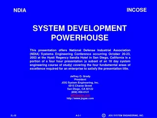
This presentation, part of a four-hour session at the NDIA Systems Engineering Conference, covers the four fundamental areas of excellence required for an enterprise to achieve successful system development. It emphasizes the importance of a sound management infrastructure and provides insights on engineering the enterprise as a system.

SYSTEM DEVELOPMENT POWERHOUSE
E N D
Presentation Transcript
INCOSE NDIA SYSTEM DEVELOPMENT POWERHOUSE This presentation offers National Defense Industrial Association (NDIA) Systems Engineering Conference occurring October 20-23, 2003 at the Hyatt Regency Ilandia Hotel in San Diego, California is a portion of a four hour presentation (a subset of an 18 day system engineering course of study) covering the four fundamental areas of excellence required for an enterprise to satisfy the presentation title. Jeffrey O. Grady President JOG System Engineering, Inc. 6015 Charae Street San Diego, CA 92122 (858) 458-0121 jeff@jogse.com http://www.jogse.com
Who Is Jeff Grady? CURRENT POSITION President, JOG System Engineering, Inc. System Engineering Assessment, Consulting, and Education Firm PRIOR EXPERIENCE 1954 - 1964 U.S. Marines 1964 - 1965 General Precision, Librascope Div Customer Training Instructor, SUBROC and ASROC ASW Systems 1965 - 1982 Teledyne Ryan Aeronautical Field Engineer, AQM-34 Series Special Purpose Aircraft Project Engineer, System Engineer, Unmanned Aircraft Systems 1982 - 1984 General Dynamics Convair Division System Engineer, Cruise Missile, Advanced Cruise Missile 1984 - 1993 General Dynamics Space Systems Division Functional Engineering Chief & Manager, Systems Development Advanced Projects Systems Engineering FORMAL EDUCATION BA Math, SDSU MS Systems Management, USC with Information Systems certificate INCOSE Fellow, Founder, First Elected Secretary AUTHOR System Requirements Analysis, System Integration, System Validation and Verification, System Engineering Planning and Enterprise Identity, System Engineering Deployment
First, what is a system? SYSTEM SYSTEM ENVIRON-MENT A collection of entities that interact through relations to achieve common purpose.
Is Your Company a Powerhouse of System Engineering? OUPUT INPUT PROCESS Or is it only wishful thinking that it could be.
The Simple Secret to Successful System Development • Define the problem • Synthesize a solution • Engineering design • Acquisition of material • Manufacturing • Prove that the solution satisfies the requirements • Accomplish all three steps within the context of a sound management infrastructure
Engineer Your Enterprise as a System ENTERPRISE COMMON PROCESS DEFINITION DEFINE DESIGN VERIFY DESIGN DEFINE PRODUCT F4232 F4333 F4231 FUNCTION F4231 F4232 F4233 FUNCTIONAL/PROCESS ORGANIZATION DEPT 210 DEPT 220 DEPT 230 ENTERPRISE FUNCTIONAL ORGANIZATIONAL STRUCTURE DEFINITION DEFINE ALLOCATION OF FUNCTIONALITY D200 TEST & EVALUATION SYSTEMS DESIGN D210 D220 D230
The Five Enterprise Functions Mapped to an Organization Structure MANAGE THE ENTERPRISE PROVIDE PROGRAM RESOURCES PERFORM ENTERPRISE BUSINESS ASSURE PRODUCT AND PROCESS QUALITY ACUIRE NEW BUSINESS
Functional Planning Structures, F-Strings F122 FUNCTIONAL DEPARTMENTSTRUCTURE (D) D262 ENTERPRISE FUNCTIONALITY (F) F122-D262 IDENTIFIES A UNIQUE ELEMENT OF WORK PLANNING LEVEL GRANULARITY BEWARE OF EXCESSIVE PLANNING DETAIL
Primary Task Responsibility PRINCIPAL DEPARTMENT LEADS IN PRACTICES DESCRIPTION TOOLS SELECTION TOOLS AND PRACTICES TRAINING
Program Planning Strings,P-Strings • PROGRAM IDENTIFICATION (P) • PERMITS COMPREHENSIVE ENTERPRISE DATABASE • PROGRAM PHASE/STAGE (S) • COORDINATES COMMON PROCESS WITH CUSTOMER PROGRAM PHASING • PROGRAM EVENTS (E) • FITS WORK INTO TIME AXIS • PROGRAM ARCHITECTURE (A) • LINKS PLANNING TO PRODUCT • LINKS PLANNING TO IPD TEAMS P05-S01-E03-A12
Typical Composite Planning String PROGRAM P-STRINGS P05-S01 -E03-A12-F122-D262 ENTERPRISE F-STRINGS ENTERPRISE PROGRAM 05 PROGRAM PHASE 01 FUNCTIONAL DEPARTMENT SUPPLYING PERSONNEL DOING PROGRAM WORK (SEE EDD APPENDIX C) PRODUCT WBS/ARCHITECTURE ITEM A12 PROGRAM EVENT 03 PROCESS (SEE EDD APPENDIX A) E00 E01 E02 E03 E04 E05 E06 CONTRACT AWARD SYSTEM REQUIREMENTS REVIEW SYSTEM DESIGN REVIEW PRELIMINARY DESIGN REVIEW CRITICAL DESIGN REVIEW FUNCTIONAL CONFIGURATION AUDIT PHYSICAL CONFIGURATION AUDIT SOW (INITIAL PLANNING STRINGS)
Define Product Requirements - Requirement Defined Something wanted or necessary. ITEM Something essential to the existence or occurrence of something else. Of what items must a system consist and how can I communicate needed characteristics for those items to designers? A necessary character- istic or attribute of some thing (or item). REQUIREMENTS ARE THE ANSWER!
Kinds of Product Requirements SOFTWARE REQUIREMENTS SYSTEMS AND HARDWARE REQUIREMENTS PERFORMANCE REQUIREMENTS (ENTITY CAPABILITIES) FUNCTIONAL REQUIREMENTS (ENTITY CAPABILITIES) NON-FUNCTIONAL REQUIREMENTS SPECIALTY ENGINEERING REQUIREMENTS INTERFACE REQUIREMENTS ENVIRONMENTAL REQUIREMENTS DESIGN CONSTRAINTS
FUNCTIONAL FACET VISION PROBLEM OBJECT SPACE FACET BEHAVIORAL FACET ANALYST Use Structured Analysis to Understand Problem Space
Systems and Hardware Structured Analysis Models • Traditional structured analysis • Flow diagramming • Enhanced flow diagramming • Behavioral diagramming • IDEF-0 • Process diagramming • State diagramming • FRAT • Quality function deployment (QFD)
F21 F22 F23 F24 F26 F11 F12 F14 F16 2.5 F13 F15 F151 F152 F153 F156 F121 F122 F123 F126 1.5.4 1.5.5 F124 F125 Functional Flow Diagramming Levels NEED F USING BASE 60 FUNCTION ID NOTATION F1 F2 F3 F5 F6 LIFE CYCLE F4 FIRST EXPANSION SECOND EXPANSION
Traditional Structured Analysis Summary FUNCTIONAL FLOW DIAGRAM F-A MATRIX FUNCTION TRANS- FORMED INTO PERFORMANCE REQUIREMENTS AND ALLOCATED TO ARCHITECTURE MANUFACTURING BREAKDOWN STRUCTURE DRAWING BREAKDOWN STRUCTURE WORK BREAKDOWN STRUCTUREINTERFACE ANALYSIS MAKE-BUY PLAN/PROCUREMENT CONFIGURATION ITEM ANALYSIS SPECIFICATION TREE DEVELOPMENT TEAM/PRINCIPAL ENGINEER ASSIGNMENT SYNTHESIZE THE ARCHITECTURE CONSTRAINTS ANALYSIS
Understand the Source of Needed Interfaces and Manage Them Well INTERNAL INTERFACE MATRIX (N-SQUARE) INTERFACE I115 ARCHITECTURE AXIS A11 A14 F4711 PERFORMANCEREQUIREMENTS F4713 FUNCTION- ARCHITECHTURE MATRIX (TRADITIONAL RAS) FUNCTION AXIS
Systematic Identification of Specialty Engineering Constraints ARCHITECTURE A11 A12 A13 A14 A15 D1 X X X 1.1 1.2 1.3 A24 1.4 A25 1.5 D2 X 2.1 X D3 X X D O M A I N S 2.2 X D4 X X X CONSTRAINT ARCH 2.3 D5 X X X X 3.1 X X D7 A11 D6 X 3.2 D7 X X X 4.1 X X D8 X X X D7 A12 4.2 X D9 X X X 5.1 X X DA X X X D7 A13 5.2 X DB X X 5.3 X DD X 6.1 X X X X D7 A21 DD X X X ARCHITECTURE-SPECIALTY ENGINEERING MATRIX (DESIGN CONSTRAINTS SCOPING MATRIX) SPECIALTY ENGINEERING REQUIREMENTS FLOW INTO THE INDICATED SPECIFICATIONS Motivated by AFSCM-375 Series
Recognize the Complete Set of Environmental Stresses SDD APPENDIX B SDD APPENDIX D
Environmental Requirements Analysis Algorithm • System environmental requirements • Define system spaces • Select standards covering those spaces • Delete unnecessary requirements • Tailor remaining parameter ranges • End item environmental requirements • Map end items to process steps • Define process step environments • Integrate multiple process step differences • Component environmental requirements • Zone end item and define zone environments • Map components to zones
MIL-STD-961E Specification StructureSystems and Hardware Template PARA 3 3.1 3.1.1 3.1.2 3.1.3 3.1.4 3.1.5 3.1.6 3.1.7 3.1.8 3.1.9 3.1.10 3.1.11 3.1.12 3.1.13 3.1.14 3.1.15 3.1.16 3.1.17 3.1.18 TITLE Requirements Functional and Performance Rqmts. Missions Threat Required States and Modes Entity Capability Requirements Reliability Maintainability Deployability Availability Environmental Conditions Transportability Materials and Processes Electromagnetic Radiation Nameplates and Product Markings Producibility Interchangeability Safety Human Factors Engineering Security and Privacy ANALYTICAL METHOD N/A N/A Mission analysis Threat analysis Traditional structured analysis Traditional structured analysis Reliability math model Maintainability math model Traditional structured analysis Availability math model Standards, EUP, Zoning Traditional structured analysis Boilerplate Standards Boilerplate Boilerplate Boilerplate Standards Standards Standards
Computer Software Structured Analysis Models • Process-oriented analysis • Flow charting • Yourdon-Demarco • Hatley-Pirbhai • Data-oriented analysis • Table normalizing • IDEF-1X • Object-oriented analysis • Early models • UML
Structured Analysis Pathways EARLY OOA MODERN STRUCTURED ANALYSIS UML FLOW CHARTING SE-UML 2010s 1950s TRADITIONAL STRUCTURED ANALYSIS
UML and TSA ComparedThe Future Revealed UNIFIED MODELING LANGUAGE (UML) STATIC MODELING DYNAMIC MODELING ACTIVITY DIAGRAM INTERACTION DIAGRAMS SEQUENCE DIAGRAM STATE CHART DEPLOY- MENT DIAGRAM COMPONENT DIAGRAM OBJECT & CLASS DIAGRAMS COLLABOR- ATION DIAGRAM USE CASE DIAGRAM ARCHITECTURE BLOCK DIAGRAM SCHEMATIC BLOCK DIAGRAM TIMELINE DIAGRAM FUNCTIONAL FLOW DIAGRAM STATE DIAGRAM TIME FACET BEHAVIORAL FACET PHYSICAL FACET FUNCTIONAL FACET TRADITIONAL STRUCTURED ANALYSIS (TSA)
The Basis For Everything We Do in System Engineering EXPANDING KNOWLEDGE SPECIALIZATION EFFECTS MAN'S KNOWLEDGE IT WON'T ALL FIT! MAN'S LIMITATIONS
We Are All Specialists - a Partial Solution BREADTH OF KNOWLEDGE DEPTH OF KNOWLEDGE ALL KNOWLEDGE GENERALIST KNOWLEDGE BASE SUBSYSTEM KNOWLEDGE BASE SPECIALIST KNOWLEDGE BASE
Physically Collocate to Recognize the Most Efficient CommunicationMedia ITEM X ITEM Y HUMAN COMMUNICATIONS - WORST INTERFACE ON PLANET EARTH!! ITEM X TEAM Electrical Engineer Mechanical Engineer Structural Dynamics Analyst Team Leader
Integration Skills INTEGRATION ELEMENT Yi INTEGRATION ELEMENT Xi DOMAIN OF THE SYSTEM ENGINEER DOMAIN Y DOMAIN X
Integration Agent IdentificationInterface Integration andLowest Common Parent Team (LCPT)
Benefits Of Product Team Organization The Most Powerful Way to Organize on a Program ORGANIZATION N-SQUARE DIAGRAM IPT 1 ICWG IPT 2 INTER-TEAM COMMUNICATION REQUIREMENT ORGANIZATIONAL MANAGEMENT IPT 3 IPT 4 WBS 1000 CROSS- ORGANIZATIONAL INTERFACE REQUIREMENT WBS 2000 PRODUCT INTEGRATION WBS 3000 WBS 4000 PRODUCT N-SQUARE DIAGRAM
The Powerful Message Offered by the “V” Model SYSTEM TEST SYSTEM REQUIREMENTS VERIFICATION REQUIREMENTS VERIFICATION REPORTS V WORK END ITEM TEST END ITEM REQUIREMENTS VERIFICATION PLANS SUBSYSTEM TEST SUBSYSTEM REQUIREMENTS COMPONENT REQUIREMENTS COMPONENT TEST DEVELOPMENT UPSTROKE DEVELOPMENT DOWNSTROKE DESIGN & INTEGRATION
Verification Atomic Structure Table 4-1 Verification Traceability Matrix SECTION 3 PARA 3.5.6.3 TITLE Transmitter Power METHOD Test SECTION 4 PARA 4.3.24 Verification String • Link specification part 3 to method and part 4 verification requirements content to form strings • Allocate verification strings to verification tasks • Collect strings about these tasks • Assign task responsibility • Plan tasks • Implement tasks on schedule • Report results and collect these reports • Form a judgment about report content
Transformation of Requirements Into Tasks (Molecules of Work) 2 1 12 11 ATOMS 13 10 9 14 18 16 4 8 7 15 22 6 3 5 29 17 23 24 21 19 20 25 26 27 35 30 31 28 38 34 39 33 36 32 50 40 45 47 42 37 48 49 41 51 44 43 46 TEST ANALYSIS DEMO EXAMINATION
Verification Tracking Matrices SPECIFICATION VERIFICATION TRACEABILITY MATRICES VERIFICATION DESIGN HAPPENS HERE UNION OF MATRICES VERIFICATION COMPLIANCE MATRIX TASK ONLY SCREEN INCLUDES EVERY VERIFICATION STRING VERIFICATION TASK TRACKING MATRIX VERIFICATION ITEM TRACKING MATRIX INCLUDES EVERY VERIFICATION TASK EACH OF WHICH IS COMPOSED OF MULTIPLE STRINGS ITEM ONLY SCREEN
Verification Documentation Pattern SYSTEM TEST AND EVAL PLANS AND PROCEDURES SYSTEM TEST AND EVAL REPORTS SYSTEM SPECIFICATION ITEM QUAL PLANS AND PROCEDURES ITEM QUAL REPORTS ITEM PERFORMANCE SPECIFICATIONS ITEM ACCEPTANCE PLANS AND PROCEDURES ITEM ACCEPTANCE REPORTS ITEM DETAIL SPECIFICATIONS
Road to Success • Define the problem • Synthesize a solution • Engineering design • Acquisition of material • Manufacturing • Prove that the solution satisfies the requirements • Accomplish all three steps within the context of a sound management infrastructure