Download
1 / 26
260 likes | 374 Vues
This senior design project at Kate Gleason College of Engineering involved creating a lightweight and modular load frame for a Scanning Electron Microscope. The objectives included specific performance requirements, vacuum compatibility, safety considerations, and staying within a budget of $7,500. The final design comprised modules such as motor and gearbox, drivetrain, gripping mechanism, control system, and vacuum interface. Detailed specifications for components like gears, power screws, bearings, and nuts were outlined. Stress analysis and design for assembly were crucial parts of the project. The team utilized LabView for control, implemented a vacuum chamber interface, and conducted stress analysis to ensure the load frame's robustness. Overall, the project aimed to benefit faculty and students in the Mechanical Engineering Department conducting metallographic research.

E N D
Design of a Tensile Load Frame for a Scanning Electron Microscope Senior Design Project 04004 Project Manager - Robert Rinefierd Faculty Mentor - Dr. Elizabeth Debartolo Kate Gleason College of Engineering
Team Members • Project Manager – Robert Rinefierd • Lead Engineer – Evan Kastner • Mechanical Engineers • Nicholas Currier, Evan Kastner, Robert Rinefierd, Blaine Stuart • Industrial Engineer • Kennedy Mogwai • Computer Engineer • Evan Brunner Kate Gleason College of Engineering
Agenda • Project Overview • Objectives and Specifications • Final Design • Manufacturing and Assembly • Production Report • Recommendations Kate Gleason College of Engineering
Project Overview • Design and construct a load frame to apply tensile loads to specimens inside the Scanning Electron Microscope (SEM) in the CIMS Materials Science Lab • The load frame should be lightweight, modular, and easy to carry between buildings • Developed for Mechanical Engineering Department faculty and students performing metallographic research • Funded by the Mechanical Engineering department Kate Gleason College of Engineering
Objectives and Specifications • Performance • 200 lbs Compression, 2000 lbs Tension • Position and Load Control • Live Displays • Implementation • Cylindrical Threaded Specimen • Remove Part of Position Frame • Evaluation • Pass Fatigue and Stress Calculations • Safety • Vacuum • Electrical Grounding Kate Gleason College of Engineering
Design Constraints • Spatial constraints • Vacuum compatibility • CIMS Materials Lab owns the SEM; Mechanical Engineering department will own the load frame • Load frame to mount to existing position fixture • Limited to existing ports for vacuum feedthrough • Budget - $7,500 Kate Gleason College of Engineering
Existing SEM Load Frames • Lehigh University concept • Tension, bending, compression • Spur gears and worm gears • US Patent • Temperature controlled • Southwest Research Institute (Dr. Davidson) • Fatigue testing capability • Custom designs for individual applications • Provided general ideas Kate Gleason College of Engineering
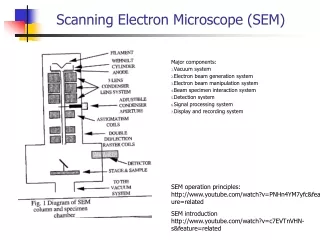
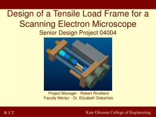
Final Design Motor and gearbox Specimen Gears Load cell Six basic Modules • Motor and Gear Box • Drivetrain • Gripping • Base and frame • Control system • Vacuum interface Grip and collar Lead screw Fixed end and base Free end Kate Gleason College of Engineering
Motor and Gearbox Selection • Motor Specifications: • Vacuum Rating – 10-7 torr • Maximum torque of 2 in·lb, driven at ~1 in·lb • Gearbox Specifications: • Vacuum Rating – 10-7 torr • Reduction Ratio – 700:1 • Maximum torque output of 1040 in·lb • Cost is high, but parts are necessary Kate Gleason College of Engineering
Drivetrain - Gears • Consists of two 2.5” diameter spur gears and a 1” diameter pinion gear. • Gearing reduction of 2.5 • Case hardened 8620 steel • Spur gears transmit torque to the power screws though keys. Kate Gleason College of Engineering
Drivetrain - Power Screws • ACME 1-10 2G threaded rods with end machining - self locking capability • Gray iron ACME nuts inserted in free end ACME thread Bearing shaft Gear shaft Keyway Kate Gleason College of Engineering
Drivetrain – Bearings and Nuts • Fixed end – bearing bores for shafts • Bearings and washers to reduce friction and add stability • Free end – ACME nuts instead of taps Kate Gleason College of Engineering
Grip Design • 3/8 – 24 threaded grip • Load cell acts as opposite grip • Easy to change samples • Standard ASTM threaded samples • Test Area • Gage length of 1 inch • Diameter of ¼ inch Collar Grip Load Cell Kate Gleason College of Engineering
Base and Frame • Purpose • Interface between load frame and SEM • Mounting surface for stage • Hold SEM position resolution device • Function • Matched bolt holes • Designed to withstand 100 lb external force (leaning) while it sits on a table. Kate Gleason College of Engineering
Control System- Physical Layout Kate Gleason College of Engineering
Controls • Control through LabView • End user definable • USB Minilab 1008 • Stock or freeware libraries • Hard emergency stop Kate Gleason College of Engineering
Vacuum Interface Vacuum chamber Available port 2 ¾ “ Flange Pro/E Model Kate Gleason College of Engineering
Stress Analysis Selected hand calculations for major components Kate Gleason College of Engineering
Stress Analysis • Verified preliminary calculations done for major parts • Shear stress, Von Mises stress, and displacement in gears, free end, and ACME shafts • Load conditions were maximum possible Kate Gleason College of Engineering
Design for Manufacture and Assembly • Assembly sequence • DFA Index – 6.23% • Minimum Number of Parts - 15 • Theoretical number of parts -61 • Estimated cost - $7223.50 Kate Gleason College of Engineering
Manufacturing and Assembly • Manufacturing Plan • Machine sequence • Tolerances • Quality checks • Total hours • Pro/E drawings • Cutting speed and feed rates • Machine tools Kate Gleason College of Engineering
Cost Analysis Kate Gleason College of Engineering
Production Report • Early March: • Completed of all aspects of mechanical design • Submitted purchase order for components • Mid-March: • Completion of detailed design including FEA analysis • Design for assembly analysis • April: • Fabrication of steel components • Development of control system with LabView • Submit order for all additional standard components • May: • Assembly and troubleshooting • Early June: • Motor and gearbox expected to arrive for assembly • Electromechanical integration and system troubleshooting Kate Gleason College of Engineering
Recommendations • Weight of load frame may be an issue • Alignment – threads are general fit rather than precision fit • Position resolution - encoder • Optimize control system after motor arrives Kate Gleason College of Engineering
Acknowledgements • Dr. DeBartolo – Faculty Mentor • Dave Hathaway and Steve Kosciol • Dave Fister, Mike Haselkorn, Newton Green – NCR³ • Charlie Clark and Frank Rheaume – Gleason Works • Ron Foster – Empire Magnetics Kate Gleason College of Engineering
Questions and Discussion Kate Gleason College of Engineering