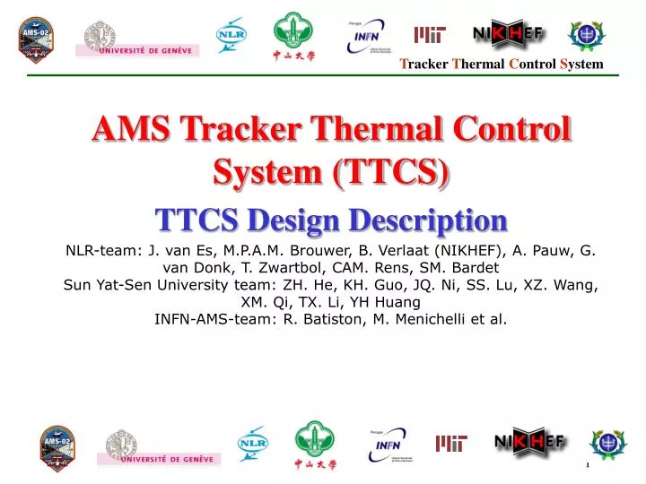
AMS Tracker Thermal Control System (TTCS) TTCS Design Description
440 likes | 566 Vues
AMS Tracker Thermal Control System (TTCS) TTCS Design Description

AMS Tracker Thermal Control System (TTCS) TTCS Design Description
E N D
Presentation Transcript
AMS Tracker Thermal Control System (TTCS) TTCS Design Description NLR-team: J. van Es, M.P.A.M. Brouwer, B. Verlaat (NIKHEF), A. Pauw, G. van Donk, T. Zwartbol, CAM. Rens, SM. BardetSun Yat-Sen University team: ZH. He, KH. Guo, JQ. Ni, SS. Lu, XZ. Wang, XM. Qi, TX. Li, YH Huang INFN-AMS-team: R. Batiston, M. Menichelli et al.
Ram heat pipe radiator Condensers Evaporator Wake heat pipe radiator TTCS com- ponent box Contents • Requirements summary • System Lay-out & Operation • Tube routing & condenser • TTCS-Boxes • Components • Pump • Heat exchanger • OHP • Safety approach • Design challenges • Integration
Requirements Summary TTCS Fluid temperature ranges • Operating Temperature loop (set-point): -15˚C / +15˚C Loop temperatures in the single-phase part can be -40˚C / +15˚C • Survival temperature: -100 ˚C / +65˚C (also for internal pressure) • Start-up temperature: -40 ˚C / + 20˚C (accumulator start-up temperature)
Requirements Summary TTCE (Electronics) in TTCS-boxes • Operating temperature: -20˚C / +85˚C • Survival temperature: -40˚C / +105˚C TTCS-box interface with USS • Operating temperature: -40˚C / +55˚C • Survival temperature: -40˚C / +55˚C • Start-up temperature (driving requirement): -40 ˚C / 10 ˚C
AMS- Tracker Thermal Control System MDP determination • Constraint 1: max allowed system fill ratio=f (MDP, MDT) • NASA : shuttle Earth Max Design Temp (MDT)= 65 °C • Given the temperature, now FRSYSTEM is only a function of MDP • AMS-team: MDP is set to 160 bar Carbon dioxide: enthalpy pressure diagram 160 160 bar, 65 °C, System Fill Ratio=density=r=580 kg/m3 • Filling accuracy: ± 4%: FRSYSTEM,MAX = 580 kg/m3 • FRSYSTEM,MIN = 536 kg/m3, this value to be used for further calculations
Requirements Summary • The overall leak tightness of the TTCS-loop is 1.0E-4 mbar.l/s CO2 at 33 bar. Leak tightness budget • Remark1: This leak tightness requirement defines (in)directly the fill rate of the TTCS as overpressurizing the system has to be avoided. • Remark2: Calculation of the equivalent He-leakrate at standard pressure and temperature should be carried out.
Requirements Summary: Environment Orbital data on the radiator is given in the following format: • MERAT temperatures of the RAM and Wake Tracker radiators. • View temperatures at the back side of the radiator • Orbital load (sun solar earth) on the RAM and Wake Tracker radiators • Orbital load at the back (inside) of the RAM and Wake radiators RAM
TTCS Operation TTCS-SS JMDC SW TTCE Manager TTCS Ground Ops & Monitoring System AMS Payload Ops & Control TM TC JMDC-CAN I/F CAN busses TTCE-A TTCE-B Architectural overview aP aS bP bS a b a b equipment equipment equipment equipment Primary Loop (PL) Secondary Loop (SL)
TTCS tube routing (schematic) RAM Condenser tubes supported by radiator diagonal strut Condenser manifold Circular tube routing using former ACC/PMT mounting hole pattern WAKE Also at bottom evaporator branch not shown Evaporator line Condenser line Two tube support beams Primary TTCS Welded connections made on site Hydraulic connectors Circular tube routing using outer cylinder generic hole pattern Secondary TTCS
Tube routing Dimensions • All tubing Do = 4 mm, Di=2.6 mm • 1 Tracker return line (combined part) Do = 6 mm, Di=2.6 mm (only in box) Additional integration issues • Wire and start-up heaters are located at evaporator tubes from box to Tracker • All tubing wrapped in MLI or located below Flange MLI. • Two support beams from top to bottom at wake side
Condenser tube routing • Condenser design • 14 capillary Inconel tubes (7 feed and 7 return lines) from each manifold to the condensers (Di= 1mm, Do=2-3 mm • Each capillary tube is wired with a wire heater to thaw the line after AMS02 complete power down. • Tubes are wrapped in MLI to minimise environmental heat leak. • Each radiator is equipped with 2 x 3 redundant Pt1000’s for switching. • Each radiator is also equipped with heater cabling A & B for health heaters. • Electrical connectors located on a bracket boxes at main radiators
Condenser tubing Manifold positions • Location at upper trunnion bridges T>-40 in all cases • Condenser lines from manifold to box T > 40 C (no freezing) • Parallel condenser lines are installed together with condenser • Manifold design Y:\Projects\AMS-Tracker\Technical\Components\condensers\CondenserManifold25feb05.pdf • brazed and welded design • Manifold orientation should be convenient for tube routing. • the manifold has a stainless steel tube end attached on the box side • tube end is orbital welded to the tube routed to the box right after installation of the condenser
Condenser Manifold location (detail) Upper trunnion bridge
Condenser tube routing • Electrical connectors (terminal blocks) are located on a bracket boxes at main radiators Picture CGS (Assenza)
Condenser Design & tube routing Tracker radiator Condenser inserts OHB Sept 2004
Condenser Design & tube routing (MGSE) Integration Bar 1 (temporary) Rod I/F Bracket Rod I/F Bracket Integration Bar 2 (temporary) TTCS Condensator Schematic OHB Sept 2004 Rod I/F Bracket
Components: Pump • Initial Data Drop for PDR is performed • Data only available for safety panel (export license agreement) • B-field test set-up is being manufactured • BBM model impeller test starting in May • Electronics design EM and QM will start next week
Components: Heat Exchanger approx 68 • two-phase to single phase plate type heat exchanger • welded housing • soldered stack of plates weld approx 87
Components: Heat Exchanger • soldered stack of plates • Soldering tests will be performed as soon as solder is delivered bottom view
Components: Heat Exchanger • Heat exchanger design is updated for box tubing • Strength calculations show 4 mm wall thickness is required • Material is stainless steel • The weld cannot be done by orbital welding (4 mm) • EM prototype is planned end of April • depends on a successful soldering test
Components: Oscillating Heat Pipe • Working Fluid FC-87 (inert, non-toxic) • Volume tubing: 2.3 ml • Fill rate 70% (i.e. 1.6 ml FC-87) • Heat supply by Minco foil heater Minco foil K5229 type 1 see specs below • Cooling by two-phase line • Operation only in cold orbits at set-points below 5 C Default disabled • Construction needs to be ruggedized by a TBD frame
Safety Approach (thermal aspects) • Safety requirement box -40 C <T < 65 C • hot case solved thermostats on power line (see lay-out) • cold case solved by USS worst case cold temperature and safety heaters as back-up (to avoid freezing and for electronics survival) • Safety requirement radiator -40 C <T < 80 C • hot case shown by analysis (this afternoon) • cold case solved by health heaters
Safety Approach (thermal aspects) • 9 parallel heater lines on PDS switch (redundant 9A and 9B) • 5 parallel lines on radiator • 4 parallel lines on condensers • Switch control by TTCE • 6 Pt1000’s (3A and 3B) • Switch performed by PDS
Safety Approach (thermal aspects) • Condenser heater lay-out 460 mm 340 mm
Design Challenges/Risks Interface temperature USS • Start-up at + 10 C USS is extreme • TEC coolers next to the pumps are foreseen in case margin is small Accumulator (design performed by CAST) • During launch temperatures above T(critical) can easily occur • Concern about bubbles in accumulator • CAST is investigating this issue by test Freezing • Freezing test to “measure” MDP • More in separate presentation
Integration aspects (welding/hydraulic connectors) Hydraulic connectors • Type: Dynatube fitting, Resistoflex Aerospace • Stainless Steel 15-5PH H1075 (-81 C to 343 C) • No leaks (MIL-F-85720) upto 8000 psi • Technical reply supplier (expected any moment) Micro-welding • Swagelock offers a “new” micro-welding technique • A meeting between AMS02 integration specialists and swagelock weld specialists is proposed to investigate the feasibility of this method
PDS thermostats Electrical schematic and routing