VLSI Design Introduction
VLSI Design Introduction. Outline. Introduction Silicon, pn-junctions and transistors A Brief History Operation of MOS Transistors CMOS circuits Fabrication steps for CMOS circuits. Introduction. Integrated circuits: many transistors on one chip. Very Large Scale Integration (VLSI)


VLSI Design Introduction
E N D
Presentation Transcript
Outline • Introduction • Silicon, pn-junctions and transistors • A Brief History • Operation of MOS Transistors • CMOS circuits • Fabrication steps for CMOS circuits
Introduction • Integrated circuits: many transistors on one chip. • Very Large Scale Integration (VLSI) • Complementary Metal Oxide Semiconductor (CMOS) • Fast, cheap, “low-power” transistors circuits
WHY VLSI DESIGN? Money, technology, civilization
Annual Sales • 1018 transistors manufactured in 2003 • 100 million for every human on the planet
Digression: Silicon Semiconductors • Modern electronic chips are built mostly on silicon substrates • Silicon is a Group IV semiconducting material • crystal lattice: covalent bonds hold each atom to four neighbors http://onlineheavytheory.net/silicon.html
Dopants • Silicon is a semiconductor at room temperature • Pure silicon has few free carriers and conducts poorly • Adding dopants increases the conductivity drastically • Dopant from Group V (e.g. As, P): extra electron (n-type) • Dopant from Group III (e.g. B, Al): missing electron, called hole (p-type)
p-n Junctions • First semiconductor (two terminal) devices • A junction between p-type and n-type semiconductor forms a diode. • Current flows only in one direction
A Brief HistoryInvention of the Transistor • Vacuum tubes ruled in first half of 20th century Large, expensive, power-hungry, unreliable • 1947: first point contact transistor (3 terminal devices) • Shockley, Bardeen and Brattain at Bell Labs
A Brief History, contd.. • 1958: First integrated circuit • Flip-flop using two transistors • Built by Jack Kilby (Nobel Laureate) at Texas Instruments • Robert Noyce (Fairchild) is also considered as a co-inventor Kilby’s IC smithsonianchips.si.edu/ augarten/
A Brief History, contd. • First Planer IC built in 1961 • 2003 • Intel Pentium 4 processor (55 million transistors) • 512 Mbit DRAM (> 0.5 billion transistors) • 53% compound annual growth rate over 45 years • No other technology has grown so fast so long • Driven by miniaturization of transistors • Smaller is cheaper, faster, lower in power! • Revolutionary effects on society
MOS Integrated Circuits • 1970’s processes usually had only nMOS transistors Inexpensive, but consume power while idle • 1980s-present: CMOS processes for low idle power Intel 1101 256-bit SRAM Intel 4004 4-bit Proc
Moore’s Law • 1965: Gordon Moore plotted transistor on each chip • Fit straight line on semilog scale • Transistor counts have doubled every 26 months Integration Levels SSI: 10 gates MSI: 1000 gates LSI: 10,000 gates VLSI: > 10k gates http://www.intel.com/technology/silicon/mooreslaw/
Corollaries • Many other factors grow exponentially • Ex: clock frequency, processor performance
Pentium 4 Processor http://www.intel.com/intel/intelis/museum/online/hist_micro/hof/index.htm
Modern transistors are few microns wide and approximately • 0.1 micron or less in length • Human hair is 80-90 microns in diameter Ref: http://micro.magnet.fsu.edu/creatures/technical/sizematters.html
Transistor Types • Bipolar transistors • npn or pnp silicon structure • Small current into very thin base layer controls large currents between emitter and collector • Base currents limit integration density • Metal Oxide Semiconductor Field Effect Transistors • nMOS and pMOS MOSFETS • Voltage applied to insulated gate controls current between source and drain • Low power allows very high integration • First patent in the ’20s in USA and Germany • Not widely used until the ’60s or ’70s
MOS Transistors • Four terminal device: gate, source, drain, body • Gate – oxide – body stack looks like a capacitor • Gate and body are conductors (body is also called the substrate) • SiO2 (oxide) is a “good” insulator (separates the gate from the body • Called metal–oxide–semiconductor (MOS) capacitor, even though gate is mostly made of poly-crystalline silicon (polysilicon) NMOS PMOS
NMOS Operation • Body is commonly tied to ground (0 V) • Drain is at a higher voltage than Source • When the gate is at a low voltage: • P-type body is at low voltage • Source-body and drain-body “diodes” are OFF • No current flows, transistor is OFF
NMOS Operation Cont. • When the gate is at a high voltage: Positive charge on gate of MOS capacitor • Negative charge is attracted to body under the gate • Inverts a channel under gate to “n-type” (N-channel, hence called the NMOS) if the gate voltage is above a threshold voltage (VT) • Now current can flow through “n-type” silicon from source through channel to drain, transistor is ON
PMOS Transistor • Similar, but doping and voltages reversed • Body tied to high voltage (VDD) • Drain is at a lower voltage than the Source • Gate low: transistor ON • Gate high: transistor OFF • Bubble indicates inverted behavior
Power Supply Voltage • GND = 0 V • In 1980’s, VDD = 5V • VDD has decreased in modern processes • High VDD would damage modern tiny transistors • Lower VDD saves power • VDD = 3.3, 2.5, 1.8, 1.5, 1.2, 1.0, • Effective power supply voltage can be lower due to IR drop across the power grid.
Transistors as Switches • In Digital circuits, MOS transistors are electrically controlled switches • Voltage at gate controls path from source to drain
A Y 0 1 CMOS Inverter
A Y 0 1 0 CMOS Inverter Y is pulled low by the turned on NMOS Device. Hence NMOS is the pull-down device.
A Y 0 1 1 0 CMOS Inverter Y is pulled high by the turned on PMOS Device. Hence PMOS is the pull-up device.
A B Y 0 0 0 1 1 0 1 1 CMOS NAND Gate
A B Y 0 0 1 0 1 1 0 1 1 CMOS NAND Gate
A B Y 0 0 1 0 1 1 1 0 1 1 CMOS NAND Gate
A B Y 0 0 1 0 1 1 1 0 1 1 1 CMOS NAND Gate
A B Y 0 0 1 0 1 1 1 0 1 1 1 0 CMOS NAND Gate
A B Y 0 0 1 0 1 0 1 0 0 1 1 0 CMOS NOR Gate
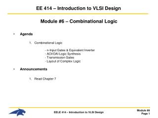
3-input NAND Gate • Y is pulled low if ALL inputs are 1 • Y is pulled high if ANY input is 0
CMOS Fabrication • CMOS transistors are fabricated on silicon wafer • Wafers diameters (200-300 mm) • Lithography process similar to printing press • On each step, different materials are deposited, or patterned or etched • Easiest to understand by viewing both top and cross-section of wafer in a simplified manufacturing process
Inverter Cross-section • Typically use p-type substrate for nMOS transistors • Requires to make an n-well for body of pMOS transistors
Well and Substrate Taps • Substrate must be tied to GND and n-well to VDD • Metal to lightly-doped semiconductor forms poor connection called Schottky Diode • Use heavily doped well and substrate contacts/taps (or ties)
Inverter Mask Set • Top view • Transistors and wires are defined by masks • Cross-section taken along dashed line
Detailed Mask Views • Six masks • n-well • Polysilicon • n+ diffusion • p+ diffusion • Contact • Metal In reality >40 masks may be needed In
Fabrication Steps • Start with blank wafer (typically p-type where NMOS is created) • Build inverter from the bottom up • First step will be to form the n-well (where PMOS would reside) • Cover wafer with protective layer of SiO2 (oxide) • Remove oxide layer where n-well should be built • Implant or diffuse n dopants into exposed wafer to form n-well • Strip off SiO2
Oxidation • Grow SiO2 on top of Si wafer • 900 – 1200 C with H2O or O2 in oxidation furnace
Photoresist • Spin on photoresist • Photoresist is a light-sensitive organic polymer • Property changes where exposed to light • Two types of photoresists (positive or negative) • Positive resists can be removed if exposed to UV light • Negative resists cannot be removed if exposed to UV light
Lithography • Expose photoresist to Ultra-violate (UV) light through the n-well mask • Strip off exposed photoresist with chemicals
Etch • Etch oxide with hydrofluoric acid (HF) • Seeps through skin and eats bone; nasty stuff!!! • Only attacks oxide where resist has been exposed • N-well pattern is transferred from the mask to silicon-di-oxide surface; creates an opening to the silicon surface
Strip Photoresist • Strip off remaining photoresist • Use mixture of acids called piranah etch • Necessary so resist doesn’t melt in next step
n-well • n-well is formed with diffusion or ion implantation • Diffusion • Place wafer in furnace with arsenic-rich gas • Heat until As atoms diffuse into exposed Si • Ion Implanatation • Blast wafer with beam of As ions • Ions blocked by SiO2, only enter exposed Si • SiO2 shields (or masks) areas which remain p-type
Strip Oxide • Strip off the remaining oxide using HF • Back to bare wafer with n-well • Subsequent steps involve similar series of steps
Polysilicon (self-aligned gate technology) • Deposit very thin layer of gate oxide • < 20 Å (6-7 atomic layers) • Chemical Vapor Deposition (CVD) of silicon layer • Place wafer in furnace with Silane gas (SiH4) • Forms many small crystals called polysilicon • Heavily doped to be good conductor
Polysilicon Patterning • Use same lithography process discussed earlier to pattern polysilicon
Self-Aligned Process • Use gate-oxide/polysilicon and masking to expose where n+ dopants should be diffused or implanted • N-diffusion forms nMOS source, drain, and n-well contact
N-diffusion/implantation • Pattern oxide and form n+ regions • Self-aligned process where gate blocks n-dopants • Polysilicon is better than metal for self-aligned gates because it doesn’t melt during later processing