Download
1 / 107
1.48k likes | 2.88k Vues
General Comparison between AISC LRFD and ASD. Hamid Zand GT STRUDL Users Group Las Vegas, Nevada June 22-25, 2005. AISC ASD and LRFD. AISC = American Institute of Steel Construction ASD = Allowable Stress Design AISC Ninth Edition LRFD = Load and Resistance Factor Design

E N D
General Comparison between AISC LRFD and ASD Hamid Zand GT STRUDL Users Group Las Vegas, Nevada June 22-25, 2005
AISC ASD and LRFD • AISC = American Institute of Steel Construction • ASD = Allowable Stress Design AISC Ninth Edition • LRFD = Load and Resistance Factor Design AISC Third Edition
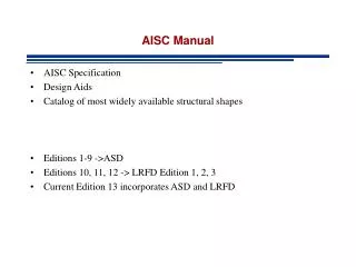
AISC Steel Design Manuals • 1963 AISC ASD 6th Edition • 1969 AISC ASD 7th Edition • 1978 AISC ASD 8th Edition • 1989 AISC ASD 9th Edition • 1986 AISC LRFD 1st Edition • 1993 AISC LRFD 2nd Edition • 1999 AISC LRFD 3rd Edition
ASD and LRFDMajor Differences • Load Combinations and load factors • ASD results are based on the stresses and LRFD results are based on the forces and moments capacity • Static analysis is acceptable for ASD but nonlinear geometric analysis is required for LRFD • Beams and flexural members • Cb computation
ASD Load Combinations • 1.0D + 1.0L • 0.75D + 0.75L + 0.75W • 0.75D + 0.75L + 0.75E D = dead load L = live load W = wind load E = earthquake load
ASD Load Combinations Or you can use following load combinations with the parameter ALSTRINC to account for the 1/3 allowable increase for the wind and seismic load • 1.0D + 1.0L • 1.0D + 1.0L + 1.0W • 1.0D + 1.0L + 1.0E • PARAMETER $ ALSTRINC based on the % increase • ALSTRINC 33.333 LOADINGS 2 3
LRFD Load Combinations • 1.4D • 1.2D + 1.6L • 1.2D + 1.6W + 0.5L • 1.2D± 1.0E + 0.5L • 0.9D± (1.6W or 1.0E) D = dead load L = live load W = wind load E = earthquake load
Deflection Load Combinationsfor ASD and LRFD • 1.0D + 1.0L • 1.0D + 1.0L + 1.0W • 1.0D + 1.0L + 1.0E D = dead load L = live load W = wind load E = earthquake load
Forces and Stresses • ASD = actual stress values are compared to the AISC allowable stress values • LRFD = actual forces and moments are compared to the AISC limiting forces and moments capacity
ASTM Steel Grade • Comparison is between Table 1 of the AISC ASD 9th Edition on Page 1-7 versus Table 2-1 of the AISC LRFD 3rd Edition on Page 2-24 • A529 Gr. 42 of ASD, not available in LRFD • A529 Gr. 50 and 55 are new in LRFD • A441 not available in LRFD • A572 Gr. 55 is new in LRFD • A618 Gr. I, II, & III are new in LRFD • A913 Gr. 50, 60, 65, & 70 are new in LRFD • A992 (Fy = 50, Fu = 65) is new in LRFD (new standard) • A847 is new in LRFD
Slenderness Ratio • Compression KL/r≤ 200 • Tension L/r≤ 300
Tension Members • Check L/r ratio • Check Tensile Strength based on the cross-section’s Gross Area • Check Tensile Strength based on the cross-section’s Net Area
Tension Members ASD ft = FX/Ag≤ FtGross Area ft = FX/Ae≤ FtNet Area LRFD Pu = FX ≤ ϕt Pn = ϕt Ag Fyϕt = 0.9 for Gross Area Pu = FX ≤ ϕt Pn = ϕt Ae Fuϕt = 0.75 for Net Area
Tension Members ASD(ASD Section D1) Gross Area Ft = 0.6Fy Net Area Ft = 0.5Fu LRFD(LRFD Section D1) Gross Area ϕt Pn = ϕt Fy Agϕt = 0.9 Net Area ϕt Pn = ϕt Fu Aeϕt = 0.75
Compare ASD to LRFD ASD 1.0D + 1.0L LRFD 1.2D + 1.6L 0.6Fy(ASD) × (1.5) = 0.9Fy(LRFD) 0.5Fu(ASD) × (1.5) = 0.75Fu(LRFD) ASD × (1.5) = LRFD
Tension Members • Member is 15 feet long • Fixed at the top of the member and free at the bottom • Loadings are: • Self weight • 400 kips tension force at the free end • Load combinations based on the ASD and LRFD codes • Steel grade is A992 • Design based on the ASD and LRFD codes
Tension Members ASD W18x46 Actual/Allowable Ratio = 0.989 LRFD W10x49 Actual/Limiting Ratio = 0.989
Tension Members ASD W18x46 Area = 13.5 in.2 FX = 400.688 kips Ratio = 0.989 LRFD W10x49 Area = 14.4 in.2 FX = 640.881 kips Ratio = 0.989
Tension Members Load Factor difference between LRFD and ASD 640.881 / 400.688 = 1.599 Equation Factor difference between LRFD and ASD LRFD = (1.5) × ASD Estimate required cross-sectional area for LRFD LRFD W10x49 Area = 14.4 in.2
Tension Members Code Check based on the ASD9 and using W10x49 FX = 400.734 kips Ratio = 0.928 Load Factor difference between LRFD and ASD 640.881 / 400.734 = 1.599 LRFD W10x49 Ratio = 0.989
Tension Members ASD Example # 1 Live Load = 400 kips W18x46 Actual/Allowable Ratio = 0.989 LRFD Example # 1 Live Load = 400 kips W10x49 Actual/Limiting Ratio = 0.989 Example # 2 Dead Load = 200 kips Live Load = 200 kips W14x43 Actual/Limiting Ratio = 0.989 Code check W14x43 based on the ASD9 W14x43 Actual/Allowable Ratio = 1.06
Compression Members • Check KL/r ratio • Compute Flexural-Torsional Buckling and Equivalent (KL/r)e • Find Maximum of KL/r and (KL/r)e • Compute Qs and Qa based on the b/t and h/tw ratios • Based on the KL/r ratio, compute allowable stress in ASD or limiting force in LRFD
Compression Members ASD fa = FX/Ag≤ Fa LRFD Pu = FX ≤ ϕc Pn = ϕc Ag Fcr Whereϕc = 0.85
Limiting Width-Thickness Ratiosfor Compression Elements ASD b/t = h/tw = LRFD b/t = h/tw =
Limiting Width-Thickness Ratiosfor Compression Elements Assume E = 29000 ksi ASD b/t = h/tw = LRFD b/t = h/tw =
Compression Members ASDKL/r≤ C′c (ASD E2-1 or A-B5-11) LRFD(LRFD A-E3-2)
Compression Members ASDKL/r > C′c (ASD E2-2) LRFD (LRFD A-E3-3)
Compression Members LRFD
Compression Members ASDLRFD Fcr / Fa = 1.681 LRFD Fcr = ASD Fa× 1.681
Compression Members ASD (ASD C-E2-2) LRFD λc = Maximum of ( λcy , λcz , λe )
Compression Members LRFD Where:
Compression Members Flexural-Torsional Buckling
Qs Computation ASD LRFD
Qs Computation Assume E = 29000 ksi ASD LRFD
Qs Computation ASD LRFD
Qs Computation Assume E = 29000 ksi ASD LRFD
Qa Computation ASD LRFD
Compression Members • Member is 15 feet long • Fixed at the bottom of the column and free at the top • Loadings are: • Self weight • 100 kips compression force at the free end • Load combinations based on the ASD and LRFD codes • Steel grade is A992 • Design based on the ASD and LRFD codes
Compression Members ASD W10x49 Actual/Allowable Ratio = 0.941 LRFD W10x54 Actual/Limiting Ratio = 0.944
Compression Members ASD W10x49 Area = 14.4 in.2 FX = 100.734 kips Ratio = 0.941 LRFD W10x54 Area = 15.8 in.2 FX = 160.967 kips Ratio = 0.944
Compression Members Load Factor difference between LRFD and ASD 160.967 / 100.734 = 1.598 Equation Factor difference between LRFD and ASD LRFD Fcr = (1.681) × ASD Fa Estimate required cross-sectional area for LRFD LRFDW10x54 Area = 15.8 inch
Compression Members Code Check based on the ASD9 and use W10x54 FX = 100.806 kips Ratio = 0.845 Load Factor difference between LRFD and ASD 160.967 / 100.806 = 1.597 LRFD W10x54 Ratio = 0.944
Compression Members ASD Example # 1 Live Load = 100 kips W10x49 Actual/Allowable Ratio = 0.941 LRFD Example # 1 Live Load = 100 kips W10x54 Actual/Limiting Ratio = 0.944 Example # 2 Dead Load = 50 kips Live Load = 50 kips W10x49 Actual/Limiting Ratio = 0.921 Code check W10x49 based on the ASD9 W10x49 Actual/Allowable Ratio = 0.941
Flexural Members • Based on the b/t and h/tw ratios determine the compactness of the cross-section • Classify flexural members as Compact, Noncompact, or Slender • When noncompact section in ASD, allowable stress Fb is computed based on the l/rt ratio. l is the laterally unbraced length of the compression flange. Also, Cb has to be computed • When noncompact or slender section in LRFD, LTB, FLB, and WLB are checked • LTB for noncompact or slender sections is computed using Lb and Cb. Lb is the laterally unbraced length of the compression flange
Flexural Members ASD fb = MZ/SZ≤ Fb LRFD Mu = MZ ≤ ϕb Mn Where ϕb = 0.9
Limiting Width-Thickness Ratiosfor Compression Elements ASD LRFD Assume E = 29000 ksi
Flexural MembersCompact Section ASD(ASD F1-1) Fb = 0.66Fy LRFD(LRFD A-F1-1) ϕb Mn = ϕb Mp = ϕb Fy ZZ ≤ 1.5Fy SZ Where ϕb = 0.9
Flexural MembersCompact Section Braced at 1/3 Points