Download
1 / 13
130 likes | 304 Vues
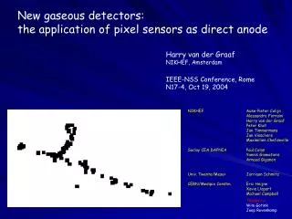
Readout of a TPC with the MEDIPIX2 CMOS chip as direct anode. Saclay/Dapnia P. Colas Y. Giomataris NIKHEF A. Fornaini H. van der Graaf J. Timmermans J. Visschers CERN/MEDIPIX2 E. Heijne Univ. Twente/MESA+ J. Schmitz. Drift Space. GEM foils. MediPix CMOS pixel sensor

E N D
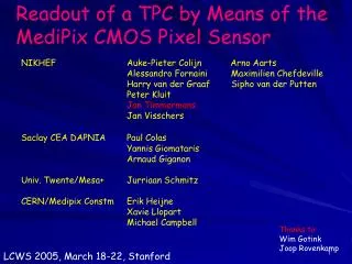
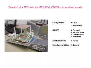
Readout of a TPC with the MEDIPIX2 CMOS chip as direct anode Saclay/Dapnia P. Colas Y. Giomataris NIKHEF A. Fornaini H. van der Graaf J. Timmermans J. Visschers CERN/MEDIPIX2 E. Heijne Univ. Twente/MESA+ J. Schmitz
Drift Space GEM foils MediPix CMOS pixel sensor Brass spacer block Printed circuit board Aluminium base plate Our GEM-equipped TPC We have constructed a small test TPC equipped with three GEM foils which can be read out by means of theMEDIPIX2 CMOS pixel sensor. The GEM foils were obtained from the CERN/Sauli/GEM group; hole-to-hole distance (hexagonal geometry): 140 µm, hole diameter 85 µm, fiducial surface 100 mm x 100 mm, thickness 50 µm.The drift volume (vol. 100x100x100 mm3) is surrounded by square wire loops, spaced 6.3 mm, put at decreasing potential. Three GEM foils are placed 7.4 mm behind the plane of the bottom wire loop; the distance between GEM foils is 1.6 mm. The anode plane, at ground potential, is 6.6 mm below the third GEM foil.
In the base plate of the chamber, a hole was cut out for the MEDIPIX2 chip: its pixel surface was flush with the (anode plane) base plate plane. The MEDIPIX2 chip contains 256 x 256 square pixels with pitch 55 µm x 55 µm giving a total fiducial sensitive area of 14.08 mm x 14.08 mm. Each pixel is equipped with a low-noise charge preamp, discriminator, two threshold DACs, a 13-bit counter and communication logic.Since a triggering system had not been implemented, we operated the MEDIPIX2 sensor by enabling the counters manually, and stop the counting after a pre-set time interval (0.1 - 10 s). After that, the counts of each pixel are read out. Drift length: 100 mm Distance between GEMs: 1.6/2.6 mm Distance bottom GEM/MEDIPIX: 6.6 mm
First events, recorded on March 29, 2003. Drift space irradiated with 55Fe quanta
No source; exposed 0.01 s No source; exposed 2 s No source; exposed 2 s Feb 9, 2004 Fiducial field: 14 x 14 mm2 Collected ionisation in 14 x 14 x 100 mm3 during exposure time No source; exposed 0.1 s 90Sr source; exposed 0.01 s
August 2002 Jeju, Korea Dean Karlen: calculation of diffusion constants; Kirsten Sachs: measurment: offset 500 m in drift versus diffusion Sept 2003: VRVS meeting: Dean Karlen: Diffusion/defocussing too large at small drift distance Induced charge effect not ruled out
Anode strip Scope 55Fe Test Pulse (edge)
Possible explanation for charge widening: • Electrons end up in low E-field region • Electrons are either ‘caught’ by drift field or diffuse to low field regions • Electrons may migrate to regions associated with adjascent GEM holes
Conclusions • - We have readout a TPC with triple GEM by means of a monolitic pixel chip as • direct anode; • The distribution of the electrons leaving a GEM hole is much wider • than the hole pitch. This may be explained by a large fraction of the • avalanche not traveling straight to the anode, but arriving much later, • after an effective de-focusing effect. • Due to the charge spread, the signal per pixel is very small, and the combination • of three GEMs and the MediPix can not detect single primary electrons; • - We expect much better results from a Micromegas/Pixel sensor combination
Thanks to: NIKHEF: Wim Gotink Joop Rovenkamp Jouri Ad Berkien, Frank de Zwart Edward Berbee, Ton Boerkamp Saclay: Arnoud • Short term plans: • Micromegas/Pixel sensor tests; • Construction of Micromegas in post-wafer process; • definition of TimePix CMOS chip