Download
1 / 25
250 likes | 399 Vues
A noiseless, kHz frame rate, imaging detector base on MCPs readout with a Medipix2. Jason McPhate, John Vallerga, Anton Tremsin and Oswald Siegmund Space Sciences Laboratory, University of California, Berkeley Bettina Mikulec and Allan Clark University of Geneva.

E N D
A noiseless, kHz frame rate, imaging detector base on MCPs readout with a Medipix2 Jason McPhate, John Vallerga, Anton Tremsin and Oswald Siegmund Space Sciences Laboratory, University of California, Berkeley Bettina Mikulec and Allan Clark University of Geneva
WFS detector for future AO systems* • kHz frame rates • Match atmospheric timescales • Many pixels - eventually 512 x 512 • More subapertures and more pixels per subaperture • Very low readout noise (< 3 e-) • Lower penalty for more pixels per subaperture • High (~80%) optical QE • Use dimmer guide stars or higher frame rates *Angel et al., “A Road Map for the Development of Astronomical AO”
Photocathode converts photon to electron MCP(s) amplify electron by 104 to 108 Rear field accelerates electrons to anode Patterned anode measures charge centroid, Count stored in digital histogram Imaging, Photon Counting Detectors
Why would you want one? • No readout noise penalty • Use as many pixels as you wish • Continuous temporal sampling to ~ nsecs • Choose integration period(s) after the fact or on the fly • Other advantages • Large area, curved focal planes • Cosmic ray = 1 count • LN2 not required • Low dark current (0.16 attoamps cm-2)
What’s the Catch? • Global Counting Rates • 1000 Shack-Hartmann spots per WFS • Kilohertz feedback rates • 1000 counts per spot for sub-pixel centroids • 1 Gigahertz counting rate! • Requires integrating detector • Quantum Efficiency • Historically Optical Photocathodes < ~15% • Silicon devices (CCDs) can get ~90% • Noiseless helps, but not that much • Requires GaAs Photocathode
Our AO detector concept An optical imaging tube using: • GaAs photocathode • MCPs to amplify to ~104 • Medipix2 ASIC readout
Medipix2 ASIC Readout • Pixelated readout for x and gamma ray semiconductor sensors (Si, GaAs, CdTe etc) • Developed at CERN for Medipix collaboration • 55 µm pixel @ 256 x 256 (abutable to 512 x [n x 256]). • Pixel level amp, discriminator, gate & counter. • Counts integrated at pixel No charge transfer! 14mm 16mm Applications: Mammography, dental radiography, dynamic autoradiography, gamma imaging, neutron imaging, angiography, x-ray diffraction, dynamic defectoscopy, etc.
Readout Architecture Pixel values are digital (14 bit) Bits are shifted into fast shift register Choice of serial or 32 bit parallel output Maximum designed bandwidth is 100MHz Corresponds to 286µs frame readout in parallel 3584 bit Pixel Column 0 3584 bit Pixel Column 255 3584 bit Pixel Column 1 256 bit fast shift register 32 bit CMOS output LVDS out
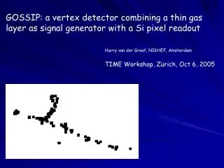
First test detector • Demountable detector • Simple lab vacuum (~10-7 Torr) • UV sensitive, no photocathode
Lab Detector Lessons • Medipix ASIC works well as MCP readout • Sub-pixel centroiding of Shack-Hartmann like spots was achieved • Optimized parameters for use in optical tube • Chevron stack of 10 µm pore MCPs (protect cathode from ion feedback) • MCP gain of about 104 (longer tube life and higher counting rates) • MCP to Medipix gap of 300 to 500 µm (Medipix wirebond clearance) • Approximately 1600 V rear field (minimize MCP charge cloud spread)
Vacuum Tube Design No GaAs capability at UCB So GaAs photocathode by industrial vendor: Means using “standard” size tube Only marginally larger than the Medipix2 device
Thick Film Ceramic Header Internal mounting/GND surface for Medipix Route ~60 Medipix signals out of vacuum Multi-layered to better match Medipix pitch Maintain hermetic seal of tube to ≤10-9 Torr Provide land pads for external I/F connectors
Parallel Readout Design • Development by ESRF • 1 to 5 Medipix2 chips • FIFO for each chip • Flat field, deadtime corrections • Optional centroid calculation • High speed serial out
Future Work (3 yr. NOAO grant) • Seal a MCP/Medipix tube with a GaAs photocathode • Perhaps a multi-alkali photocathode tube (@UCB) • Finalize and build parallel readout • Test at AO laboratory at CFAO, U.C. Santa Cruz • Test at telescope
Univ. of Barcelona University of Cagliari CEA CERN University of Freiburg University of Glasgow Czech Academy of Sciences Mid-Sweden University University of Napoli NIKHEF University of Pisa University of Auvergne Medical Research Council Czech Technical University ESRF University of Erlangen-Nurnberg Acknowledgements This work was funded by an AODP grant managed by NOAO and funded by NSF Thanks to the Medipix Collaboration: