Download
1 / 22
220 likes | 388 Vues
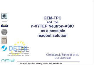
GEM-TPC and the n-XYTER Neutron-ASIC as a possible readout solution. INFM - Perugia Forschungszentrum J ülich Hahn Meitner Institut - Berlin Ruprecht Karls Universit ä t - Heidelberg AGH University of Sci. and Tech. - Krakow. GEM-TPC Kick-Off Meeting, Vienna, Feb. 8th and 9th.

E N D
GEM-TPCand then-XYTER Neutron-ASIC as a possiblereadout solution INFM - Perugia Forschungszentrum Jülich Hahn Meitner Institut - Berlin Ruprecht Karls Universität - Heidelberg AGH University of Sci. and Tech. - Krakow GEM-TPC Kick-Off Meeting, Vienna, Feb. 8th and 9th
DETNI Detectors for Neutron Instrumentation Develop and prototype three different advanced area sensitive detector systems within FP-6 Gd/Si Micro Strip Gd/CsI MSGC CASCADE GEM for very high rates (108 Hz) mm and sub mm resolution highest possible detection efficiency __ as a supplement: develop the first dedicated Neutron detector readout ASIC universal to these detectors
DETNI Collaboration S.S. Alimova, A. Brognab, S. Buzzettib,c, W. Dabrowskid, T. Fiutowskid,B. Gebauera, G. Kemmerlinge, M. Kleinb, C. Petrillof, F. Sacchettif, Ch.J. Schmidtg, K.H. Soltveitb, R. Szczygield,h, Ch. Schulza, C. Thielmanne, U. Trunkb, P. Wiacekd, Th. Wilperta aHahn-Meitner-Institut Berlin, Glienicker Str. 100, D-14109 Germany bPhysikalisches Institut der Universität Heidelberg, Philosophenweg 12, D-69120 Heidelberg, Germany cINFM & Dipartimento di Elettronica et Informazione, Politecnico di Milano, Piazza Leonardo da Vinci 32, Milano I-20133, Italy dFaculty of Physics and Applied Computer Science, AGH University of Science and Technology, al. Mickiewicza 30, 30-059 Krakow, Poland eCentral Institute for Electronics, Research Centre Jülich, 52425 Jülich, Germany fINFN & Dipartimento di Fisica, Universita di Perugia, Via A. Pascoli, Perugia I-06123, Italy gGesellschaft für Schwerionenforschung, Planckstr. 1, 64291 Darmstadt, Germany hInstitute of Nuclear Physics, Polish Academy of Sciences, ul. Radzikowskiego 152, 31-342 Krakow, Poland
A157Gd/Si Microstrip Detector • Eth(5s) 10 keV • ENC 550 e- (20 - 30 pF) • cps (global) 2.5 x 10⁷ • cps/strip 7.5 x 10⁴ • dT (x/y) 4 ns • Size 51 mm x 51 mm • No. of strips 640 • Pitch 80 µm • dx 50 - 100 µm • ES 29 - 250 keV Caterina Petrillo et al, Peruggia and Milano
B 157Gd/CsI Low-pressure MSGC Detector Solid converter gas detector hybrid Each Coordinate: 400 channels on 250mm event multiplicity 3.5 strips Maximum rate per channel: 950kHz Burckhard Gebauer et al, Berlin
CASCADE: Multiple Boron Layers on GEMs 10B + n 7Li + + 2.79 MeV ( 6%) 3838 b 7Li*+ + 2.31 MeV (94%) • GEMs can be operated to be transparent for charges! they can be cascaded! • Each one can carry two Boron layers • Last one operated as amplifier Cumulate 5% single layer detection efficiency to give 50% for thermal neutrons (1.8Å) need 10 cascaded GEM-foils Christian Schmidt et al
Assembled 2D-200 CASCADE Detector Power supply and thermal management Detector entrance window (100 µm Al) FPGA based readout board ASIC frontend-electronic GEM-foils coated with 10B and 2D readout structure
Radiography with the 2D-200 CASCADE Detector System old PC-Mouse Water Flow-Indicator Data taken at instrument EKN at FZ Jülich Tesa-Tape Dispenser Pixel Size: 1.56mm
Neutron Events vs. HEP- and HIP-Events Character of Data and Challenges in Data Processing High Energy/ Heavy Ion • Periodic spill or bunch crossing • Detectors with millions of pixels • MByte of data per event • Correlations between data across detector system Neutrons • Statistically incoming Neutrons • Currently ~40 000 pixels, future up to 106 • ~ 8 byte of data per event • All events of interest (up to 108 per sec) • Pixel occupancy may be very high • No fast trigger strategy (no data correlation) but: • few events of interest • low pixel occupancy • low event rate
Statistical Nature of Neutron Data Mathematically • The number of events in a time interval is Poisson distributed for t < ms • The time between successive events is exponentially distributed Practical consequences are: • New events to be expected any time, no trigger available • Events come in completely irregularly • Only the mean rate is well defined • Practical readout is bandwidth limited, need to specify maximum mean rate at maximum acceptable data loss (dead time). • 10% max. data loss demands 10 x (mean rate) as readout bandwidth
N-XYTER: The DETNI Neutron Detector Readout ASIC Neutron – X, Y, Time and Energy ... R Architecture: Front-End: • 128 channel data driven charge sensitive front-end • Front end for either polarity input signals • Charge sensitive pre-amp and peak detector • Time stamping with 1 ns resolution • Purely data driven, autonomous hit detection Readout: • Per channel analogue energy and digital time stamp FIFO (1ns resolution) • De-randomizing, sparcifying Token Ring readout at 32 MHz
DETNI Data Driven Front-End:towards N-XYTER comparator Time WalkCompensationcircuit triggertimestamp FASTshaper 30ns peaking PDH reset chargepreamp chargeinput SLOW shaper(2 stages) 150ns peaking time Peakdetector & hold, free running pulse height output The DETNI ASIC 1.0, a front-end evaluation chip in AMS 0.35µ
FAST channel SLOW channel ENC 26.9 e/pF + 200 e 12.7 e/pF + 233 e peaking timea (1% to 99%) 18.5 ns 139 ns Analogue Pulses, Peaking Time, Front-End Noise Engineered for 30 pF, giving 1000 e 600 e power consumption: 12.8 mW per channel; OK for neutrons!
Token Ring Readout Process Token Cell processes token: on token, check for data, either initiate readout in clock cycle or pass forward token token cycle • Periodic readout at 32 MHz • Token asynchronously passes from channel to channel in search of data • Within one readout cycle token could pass through all channels • If token encounters occupied channels, data readout is initiated. • After readout the token passes to the next channel. Analogue FIFO Disc. Timestamp FIFO data readout bus
Token Ring Architectural Pros/Cons • High Efficiency • Empty channels automatically skipped in readout process • Built-in fair distribution of readout bandwidth, automatic bandwidth focussing • Built-in De-Randomization: 100% bandwidth used on data • High Modularity • Identical, periodic internal structure for all the channels • ASICs with variable number of channels can be realized • unused channels remain unnoticed: no use of bandwith, just power • Error Robustness • Any problematic channel (e.g. continuously firering) will divert and occupy a maximum of 1/nth of the bandwidth. • Built-in, non-perfect readout probability avoids unrecoverable logic deadlock: Problematic situations like any kind of pile-up, logic hang-ups or glitch cause mere deadtime but the “show will go on”. But: Data needs to be tagged with a time-stamp Data needs to be resorted and re-bunched after readout
1 2 3 4 5 6 7 8 9 10 11 12 13 0.2 0.15 Probability 0.1 We loose from here on 0.05 0 0 1 2 3 4 5 6 7 8 9 10 11 12 Modelling FIFO Occupancy Poisson Distribution(l): e.g.: fifo depth n = 4, so expect 4 events during readout if incoming rate equals maximum readout rate. l = 4. FIFO can virtually be filled with up to 2*n events with no data loss since n elements are read while data comes in.
N-XYTER Submitted via CMP, 250 Dies Available 8 LVDS output lines at 4 x 32MHz: time stamp, channel no. + 1 differential, analogue output 128 analogue inputs poisson distributed at 32 MHz total average input rate AMS CMOS 0.35µ with thick metal four
First Test PCB for N-XYTER (DETNI/Heidelberg) LVDS/ TTL out 64/128 input lines analogue out Questions Addressed: • Animate the chip • Check Programming • Check Clock Operation • Check Analogue Performance infra- structure
Testing, first preliminary conclusions • all slow control operative • change of polarity works • somewhat complicated 1ns time stamp clock works • gray code is operative • analogue trigger, time stamp latching operative • data transfer through token ring is operative • testing features operative Now we need to get quantitative!
46 I2C slow control registers, 16 + 128 DACs Integral Non-Linearity ~ 2 LSB, no missing code
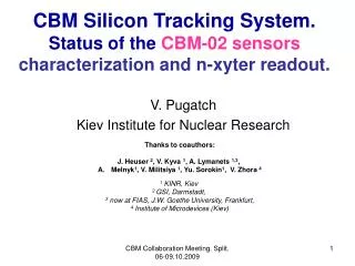
Silicon Strips at GSI • CBM is having test devices made: CIS Erfurt • 50 micron pitch 256 x 256 channels • 80 micron pitch 256 x 256 channels • ~ 50 mm size, 15° stereo angle devices for telescope setup and other tests 12.8 mm design studies for the CBM Si-strip tracker c.f. talk by Johann Heuser 20.5 mm