Download
1 / 67
670 likes | 870 Vues
Development of a Stereoscopic Projection System. Thesis Proposal. V 2 ..2. Introduction to 3D Projection Systems 3D Applications. Medical Scientific Engineering Education Entertainment Military Advertising. Introduction to 3D Projection Systems Budget for the example systems.

E N D
Development of a Stereoscopic Projection System Thesis Proposal V 2..2
Introduction to 3D Projection Systems3D Applications • Medical • Scientific • Engineering • Education • Entertainment • Military • Advertising
Introduction to 3D Projection Systems Budget for the example systems From www.inition.co.uk
Project Preface • If you want a Stereoscopic System, But you have small budget. What is our alternative?
Project PrefaceProblem • Commercial 3D stereoscopic systems are too expensive for average users because they require a customized projector. 245,800 Bath!!! 40,000 Bath , OK!!
Project PrefaceIdea • If we can adapt a common projector to project 3D stereopsis without modifying them,the cost of the system can be reduced. 40,000 Bath , OK!! 6
Project PrefaceObjective • The objective of this project is to develop a shutter-glass based stereoscopic upgrade kit for an off-the-shelf DLP projector. 40,000 Bath , OK!! 7
Type of Displays Stereoscopic Volumetric Autostereoscopic Stereoscopic 3D Display
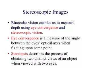
Principle of Stereoscopic Stereoscopic Autostereoscopic Volumetric Stereoscopic • Invented By Charles Wheatstone in 1838. • Stereopsis is depth perception from binocular visions through exploitation of parallax. • Use two correspondence images to create an illusion of depth. 3D Display
Autostereoscopic • Lenticular lens • Sweeping light source
StereoscopicHMD • HMD (Head Mounted Display) • Disadvantage • Low Resolution • Heavy ,Inconvenient • Expensive ($1399-$145,000)
Stereoscopic 2-Color Anaglyph • 2-Color anaglyph • Use two of color filters. • Advantage • Simple • Disadvantage • Color Distortion • Anachrome is an Anaglyph Variant • Anaglyph only in the border of object,and preserve the color in the center object. This technique can reduce color distortion.
Stereoscopic ChromaDepth • Use prism. • Advantage • Can be viewed without glasses. • Disadvantage • Colorless ภาพChromaDepth แผ่นปริซึม ฉากรับภาพ จุดโฟกัส การมองเห็นภาพสามมิติจากภาพสองมิติแอนะกลิฟ
Stereoscopic Polarizing Glass • Advantage • Polarized eyeglasses are cheap. • Disadvantage • Not feasible to use with LCD projector. • Viewers need to keep their head level to prevent left and right channels bleedover the opposite channel. • Need a polarization preserving screen.
Stereoscopic Shutter Glass • Create 3D Stereoscopic illusion by Switching projected picture for left and right eyes continuously. • The appeared image and shutter glasses have to be synchronize.
Stereoscopic Shutter Glass • Shutter Glass Mechanical ฉากฉายภาพ Shutter ฉากรับภาพ จุดโฟกัส Left Eye Right Eye
Tracking System • Position Tracker System • Mechanical Tracker • Ultrasonic • Electromagnetic • Optical • Laser • Marker • Face Recognition
Concept of the Proposed SystemSynchronization Problem • The problem is , • When we use common projector in projecting 3D stereoscopic signal, the projected picture isn’t synchronized with the shutter glasses. • Cause of problems • The mechanism of DLP Projector • Micromirror and its operation. • Color Wheel Display External Box Shutter Glass Shutter Glass Sync
Concept of the Proposed System Cause of problem, DLP Technology • DLP (Digital Lighting Processor) • DMD (Digital Micromirror Device) • MEMS (Micro Electro-Mechanism)
Concept of the Proposed SystemSolution • The cause of the problem • The interval in digital lighting processor causes the appeared frame on the screen delayed. • Ghosting Effect • Frame Dropped • Rainbow Effect, Especially on DLP Projector. • Solution • Change synchronization source from graphic card output signal to the marker on appeared picture on the screen. Dongle Shutter Glass Sync Sync Display External Box Shutter Glass Graphic Card Shutter Glass Sync
Proposed System Com : Computer MIB : Marker Insertion Box Proj : Projector Tcam :Tracker Camera ODD : Opto Detection Device ShtCnt : Shutter glasses Control
Proposed SystemComponent Details • Components that have to be developed. • MIB : Marker Insertion Box • Insert the marker in projected picture. • There is switch on the box for reset, If the pictures from left and right eyes were swapped. • ODD : Opto Detector Device • Detect the appearance of the synchronization marker on screen, And transmit signal to the shutter glasses control box if there were a marker appeared. • Easy to attached on Left-top of the screen.
Proposed SystemComponent Details • ShtCnt : Shutter glasses Control • Synchronize shutter glasses timing to the picture by detecting signal from ODD. • Can slice timing from synchronization signal by using digital PLL. • Tcam: Tracker Camera • Track viewer head position by the shutter glasses attached camera. • Locate head position by looking at the implanted LED marker on the screen. • Can be fused with angular acceleration sensor.
Proposed System Buy or Build Off the Shelf Developed Components
Proposed SystemBudget Comparison * Tracker :InterSense IS-1200 VisTracker * Computer and Software are omited
Proposed SystemMIB : Function • Synchronization System • Marker Insertion Box • Opto Detector Device(ODD) • Shutter Glass Controller • The inserted marker will be appear on top-left of the screen. ODD
Pixel Clock Generator VSync HSync Counting Circuit Horizontal Counting Circuit Vertical Switch (a) Compare-Horizontal Compare-Vertical Comparator (b) FPGA Marker (c) To Projector VGA Source (d) Switch Proposed System MIB : Implementation • Synchronization System • Marker Insertion Box • Opto Detector Device(ODD) • Shutter Glass Controller
Proposed System ODD • Synchronization System • Frame Marker Insertion • Opto Detector Device(ODD) • Shutter Glass Controller • Shutter Glass Controller Computer (WinSGL Scheme)
Proposed System ODD : WinSGL • Synchronization System • Fix Frame-Dropped Problem. • Long Delayed - Frame Synchronization • SoftGenlock • Short Delayed – Signal Synchronization • Hardware GenLock (SGI / GeForce (SLI) / nVidia) • Software (WinSGL)
Shutter Glass Time Base ODD Sequential Circuit Glass Control Proposed System Shutter Glasses Controller • Synchronization System • Frame Marker Insertion • Opto Detector Device(ODD) • Shutter Glass Controller • Implemented on Microcontroller. ÷N Increase / Decrease Time base PLL
Proposed System Shutter Glasses Control • LCD Technology in shutter glasses • Problem in controlling Shutter Glass • Spectrum Transparency • Ghosting Effect : LCD Responding
Proposed System : Shutter Glasses Control LCD Technology in shutter glasses • LCD (Liquid Crystal Display) • TN (Twisted Nematic) • TFT (Transistor Film Transistor)
Proposed System : Shutter Glasses Control LCD Technology in shutter glasses • LCD (Liquid Crystal Display) • TN (Twisted Nematic) • TFT (Transistor Film Transistor) Twist DirectionBipolarity CapacitanceDead Band
Proposed System : Shutter Glasses Control Ghosting Effect • Slow response. • LCD molecular momentum and capacitance. • Can be reduced by adding an Interval between control sequences. • Proposed by Kunz ,2001
Shutter Glass Time Base ODD Sequential Circuit Glass Control Proposed System : Shutter Glasses Control Implementation Plan Dead Band Generator ÷N Increase / Decrease Time base PLL Bipolar Generator
Proposed SystemTracking System • Synchronization System • Frame Marker Insertion • Dongle, Snap on screen Device • Shutter Glass Controller • Head Tracker • IR Marker Implanted Screen& IR Camera • Vision Base TrackingSoftware
Proposed SystemTracking System • Vision based tracker system. • Integrate angular acceleration sensor for a better respond.
Proposed System : Tracking System Implementation • Head Tracker • IR Marker Implanted Screen& IR Camera • Vision Based TrackingSoftware • Localization based on correspondences from the features in known environment.