Download
1 / 40
410 likes | 713 Vues
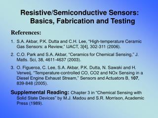
Resistive/Semiconductive Sensors: Basics, Fabrication and Testing References: S.A. Akbar, P.K. Dutta and C.H. Lee, “High-temperature Ceramic Gas Sensors: a Review,” IJACT, 3[4], 302-311 (2006). C.O. Park and S.A. Akbar, “Ceramics for Chemical Sensing,” J. Matls. Sci, 38, 4611-4637 (2003).

E N D
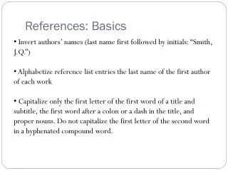
Resistive/Semiconductive Sensors: Basics, Fabrication and Testing • References: • S.A. Akbar, P.K. Dutta and C.H. Lee, “High-temperature Ceramic Gas Sensors: a Review,” IJACT, 3[4], 302-311 (2006). • C.O. Park and S.A. Akbar, “Ceramics for Chemical Sensing,” J. Matls. Sci, 38, 4611-4637 (2003). • O. Figueroa, C. Lee, S.A. Akbar, P.K. Dutta, N. Sawaki and H. Verweij, “Temperature-controlled CO, CO2 and NOx Sensing in a Diesel Engine Exhaust Stream,” Sensors and Actuators B, 107, 839-848 (2005). • Supplemental Reading:Chapter 3 in “Chemical Sensing with Solid State Devices” by M.J. Madou and S.R. Morrison, Academic Press (1989).
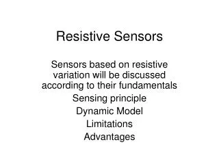
Ceramic-based Resistive Sensors • Bulk conduction based (dense) • TiO2, BaTiO3, CeO2 and Nb2O5 • Metal/Oxide junction based • Schottky diode (Pd/SnO2, Pt/TiO2) • MOS/MISFET • Surface/intergranular controlled (porous) • SnO2, TiO2
n = 4 n = 6 Bulk-conduction based Sensors • T dependence in the • p-type region is negligible • Think about a proper dopant • that can make Ea ~ 0 Fig. The change in conductivity of BaTiO3 with oxygen pressure at temperatures from 600 to 1000C (50C intervals)
Metal/Oxide Junction Controlled Sensors: a. Schottky-diode type The I-V characteristic of a Schottky diode is described by the thermo-electronic emission as Schottky: Pd/SnO2, Pt/TiO2 Ohmic: Ag, Au A*: Richardson const. V: bias voltage Vs: Schottky barrier (depends on occupation of the surface states)
Schottky Contact Ohmic Contact
b. MOS/MISFET type The threshold gate voltage, upon exposure to the hydrogen-containing atmosphere, shifts by DV, compared to gate voltage without hydrogen • Accumulation of H+ creates a • dipole layer lowering DV • Can be measured by I-V or C-V • - Shifts threshold voltage in FET Fig.(A) Schematic picture of the metal-insulator region upon chemisorption of hydrogen atoms (B) the hydrogen-induced shift of the threshold voltage characteristics of MISFET (C) the hydrogen-induced shift of the capacitance-voltage curve in MOS Capacitor.
Surface/intergranular Controlled Semiconductive/resistive
Physisorption vs. Chemisorption • Practically no energy is needed for physisorption • As the molecule approaches it polarizes the surface inducing dipole/dipole interaction • Further approach increases the energy of the system, so physisorbed species is stably located at rp • There is a little energy for • desorption • DHphy < 0.2 eV (~5 kcal/mol) Lennard-Jones model for physisorption and chemisorption - Molecule can dissociate into atoms. As the atom approaches, a strong interaction involving e- transfer occurs to form a chemical bond at a distance rc. - Direct chemisorption is less likely because of large energy for dissociation (DED) - Chemisorption follows physisorption that requires an activation barrier of DEA for adsorption and DHchem for desorption DHchem > 1 eV (~23 kcal/mol)
Adsorption Isobar (coverage as a function of T at a fixed P) • Coverage decreases • with T because of • increased desorption • Region I is dominated • by physisorption • In region II, initially • chemisorption proceeds • readily since DEA is low • - As coverage increases • DEA increases, but T • helps overcome this as • long as desorption rate • is lower than adsorption • rate up to region III • Fig. Typical adsorption isobar (coverage as a function T at a fixed pressure: • physisorption, (II) irreversible transition (equilibrium physisorption is readily • achieved, equilibrium chemisorption falls short) and (III) chemisorption
[ ]s is the concentration of adsorbates on the surface O- and OH- increase R, but H2O+ donates an e- to decrease R I: adsorbed water molecules dominate, blocking off O-. II: as T rises water desorbs permitting an equilibrium surface oxygen, also dissociative chemisorption of water to form OH- III. Combination of NTC and desorption of OH-. , Fig. Schematic plots of equilibrium isobars for and and the resistance of SnO2 as a function of temperature known as the sigmoidal curve
Depletive adsorption of X as X- on an n-type semiconductior: (a) flat band (b) after adsorption, and adsorption of X as X+ on a p type semiconductor: (c) flat band (d) after adsorption - Direction of e- transfer depends on the difference of energy of surface state and Fermi energy of the oxide. - If surface energy is lower, e- from CB of n-type (depletive adsorption) and VB for p-type (cumulative adsorption; abundant e- exit in the VB. This is why p-type is a better catalyst). n-type: SnO2, ZnO, TiO2 p-type: NiO - If surface energy is higher, the reverse occurs.
qVs qVs Sensing mechanism of oxide-based sensors CO CO2 Absorbed oxygen O- O- O- O- O- O- O- O- Conduction band electrons O- O- O- O- e- O- O- O- Depletion region O- O- O- O- O- O- O- O- O- O- O- O- O- O- Semiconductor Particles O- O- Ec EF Ev
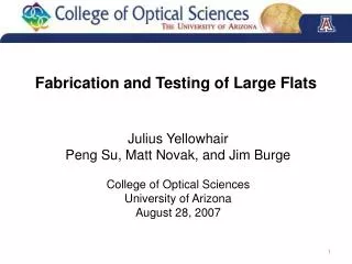
Sensor Structures and Materials For T: 300 – 400 C needs >500 mW; heated by Ir-Pd or Cr alloy wire Bulk Type: Bulk type gas sensors with: (a) direct heating and (b) indirect heating
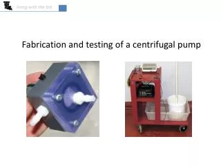
Thick Film Type: Requires < 200 mW <100 mW (thin-film) Thick film gas sensors (1x2mm) [taken from CAOS Inc.]
Selective Design Concentration profile of gas species across the thickness for a thick porous film. Electrodes can be placed on top, at the bottom or on the side of the sensing layer. S: side electrode B: bottom electrode U: upper electrode. For B, path 1 or 2 depends on the gap between the electrodes and film thickness For narrow gap, sensitivity comes from reaction of the gas with the material in the gap For wide gap, reactivity and thickness simultaneously control - if too reactive, it gets reacted at the outer surface, low sensitivity - if low reactivity, high sensitivity
Various positions of electrodes used in the construction of the sensor (b) Various configurations of electrodes used in the construction of the sensor ([i]: interdigitized, [ii]: 4 point micro-contact and [iii]: planar). • Bottom electrode is good for selectivity • - bottom electrode with small gap • to detect poorly reactive gas • if the gap is large compared to • thickness, highly reactive gas • can be selectively detected.
Fig 34 Various alcohol breath analyzers using a semiconductor sensor (adopted from: http://www.dui.com, http://www.intox.com, and http://www.lifeloc.com)
CO Sensor: Fabrication and Testing Thick-film Technology References: 1. Ceramic Materials for Electronics: Processing, Properties and Applications, Edited by Relva C. Buchanan, Marcel Dekker, Inc. (1991), pp. 435-488 2. Handbook of Thick Film Technology by P.J. Holmes and R.G. Loasby, Electrochemical Publications Ltd., 1976. 3. Interfacial Phenomena in Dispersed Systems by Jean-Louis Salager, Universidad de Los Andes (1994). 4. O. Figueroa et al., “Temperature controlled CO, CO2 and NOx sensing in a diesel engine exhaust stream,” Sensors and Actuators B, 107, 839-848 (2005).
Key Parameters in Screen Printing Ink viscosity, h = t/g - h = 10 Pa-sec; g = 103 sec-1 when squeegee traverses the screen - h < 103 Pa-sec for < 15 min. so that leveling can occur; g = 1 sec-1 due to surface tension - after leveling h > 104 Pa-sec; g = 10-2 driven by gravity
Wetting – main property is the surface tension of the various components. Wetting is determined by the contact angle – (1) for angle between 90 and 180, no wetting; (2) For angle between 0 and 90, wetting. Contact angle is determined by surface tension of sv, lv and interfacial (sl). In liquid-based systems, surface tension of lv is usually affected by additives. Examples – (1) long chain polysiloxanes (can affect adhesion; short chain polysiloxanes do not affect adhesion); (2) polyacrylates low surface tension; they float to the surface decreasing the surface tension http://www.cibasc.com/index/ind-index/ind-paints_and_coatings/ind-paints_and_coatings_theory.htm
Dispersant – molecules with only one polar group anchors on the surface of particle and the tail (non-polar end) extends in the medium, keeping the particles separate. The molecular weight determines tail length and hence the separation distance. The bonding can be one of the following. • Hydrogen bonding (6 kcal/mol); (2) dipole-dipole interaction (3-4 kcal/mol); (3) London-van der Waals (2 kcal/mol) • Example: Polyurethane polymers (PUR, viscosity reducing agent), polyacrylate • Amount to add – 10% of the oil adsorption value (OAV). • TiO2 – OAV (19) – amount of dispersant 1.9% • Fe2O3 – OAV (35) – amount of dispersant 3.5% http://www.cibasc.com/index/ind-index/ind-paints_and_coatings/ind-paints_and_coatings_theory.htm
Resistive/semiconductive type thick-film sensors Screen printed sensor
O- O- O- O- e- e- e- e- + CO: Resistance O- O- O- O- h* h* h* h* + CO: Resistance Selective Sensor Based on a Composite Anatase Rutile What happens when Anatase and Rutile are combined? Parallel conduction pathways
n/p Composite as a Selective CO Sensor • 75% Rutile composite has simultaneous n-n and p-p percolation • different single-phase response for each gas Single-Phase Sensor Response 75% Rutile Composite CH4 CO
H i g h - T e m p c e m e n t T h e r m o c o u p l e S l i t f o r g a s flow S e n s o r f i l m G o l d 4 - b o r e e l e c t r o d e s C l o s e d - e n d a l u m i n a t u b e a l u m i n a t u b e Sensor Probe for Field TestConfiguration of Sensor Tested at CAR Temperature should be controlled by a heating strip Sensor should be shielded from high-velocity gases and particulates