
Bridges and spanning tree protocol
E N D
Presentation Transcript
5: DataLink Layer Bridges and spanning tree protocol • Reference: Mainly Peterson-Davie
5: DataLink Layer Bridges • Link layer device • stores and forwards Ethernet frames • examines frame header and selectively forwards frame based on MAC dest address • when frame is to be forwarded on segment, uses CSMA/CD to access segment • transparent • hosts are unaware of presence of bridges • plug-and-play, self-learning • bridges do not need to be configured
5: DataLink Layer Forwarding How do determine to which LAN segment to forward frame? • Looks like a routing problem...
5: DataLink Layer Self learning • A bridge has a bridge table • entry in bridge table: • (Node LAN Address, Bridge Interface, Time Stamp) • stale entries in table dropped (TTL can be 60 min) • bridges learn which hosts can be reached through which interfaces • when frame received, bridge “learns” location of sender: incoming LAN segment • records sender/location pair in bridge table
5: DataLink Layer Filtering/Forwarding When bridge receives a frame: index bridge table using MAC dest address if entry found for destinationthen{ if dest on segment from which frame arrivedthen drop the frame else forward the frame on interface indicated } else flood forward on all but the interface on which the frame arrived
5: DataLink Layer Bridge example Suppose C sends frame to D and D replies back with frame to C. • Bridge receives frame from from C • notes in bridge table that C is on interface 1 • because D is not in table, bridge sends frame into interfaces 2 and 3 • frame received by D
5: DataLink Layer Bridge Learning: example • D generates frame for C, sends • bridge receives frame • notes in bridge table that D is on interface 2 • bridge knows C is on interface 1, so selectively forwards frame to interface 1
5: DataLink Layer Needed: Routing • Complex large LANs need alternative routes • Load balancing • Fault tolerance • Bridge must decide whether to forward frame • Bridge must decide which LAN to forward frame on • Routing selected for each source-destination pair of LANs • Done in configuration • Usually least hop route • Only changed when topology changes
5: DataLink Layer Spanning Tree • Bridge automatically develops routing table • Automatically update in response to changes • Frame forwarding • Address learning • Loop resolution Reference: Stallings
5: DataLink Layer Frame forwarding • Maintain forwarding database for each port • List station addresses reached through each port • For a frame arriving on port X: • Search forwarding database to see if MAC address is listed for any port except X • If address not found, forward to all ports except X • If address listed for port Y, check port Y for blocking or forwarding state • Blocking prevents port from receiving or transmitting • If not blocked, transmit frame through port Y
5: DataLink Layer Address Learning • When frame arrives at port X, it has come form the LAN attached to port X • Use the source address to update forwarding database for port X to include that address • Timer on each entry in database (reset whenever frame received) • Each time frame arrives, source address checked against forwarding database
5: DataLink Layer Loop of Bridges
5: DataLink Layer Loop Resolving • The simple learning mechanism described fails in presence of loops in the LAN • Loops may be present by mistake, or deliberately provided for redundency • This problem is resolved by running a distributed spanning tree algorithm
5: DataLink Layer Spanning Tree Algorithm • Creates a logical, or “active” topology that behaves like a spanning tree • Makes alternate bridges redundant • Is run periodically, so will discover failures and use alternate bridges if necessary Reference: Fred Halsall: “Data Communications, Computer Networks and Open Systems”, 4th Edition.
5: DataLink Layer Spanning tree • Think of the LAN as a graph that possibly has loops (LAN segments as nodes, bridges as edges) • The spanning tree is a subgraph of this graph that covers all vertices (LAN segments), but contains no cycles.
5: DataLink Layer Spanning tree algorithm • Spanning tree algorithm is a protocol used by a set of bridges to agree upon a spanning tree for a particular extended LAN. • Essentially, this means that each bridge decides the ports over which it is and is not willing to forward packets. • Some ports (or even entire bridges) may not participate in a spanning tree • How does the bridge select the ports to include (/exclude)?
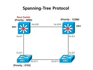
5: DataLink Layer Spanning Tree Algorithm • Working: Bridges regularly exchange frames known as Bridge Protocol Data Units (BPDUs). This exchange does the following: • Each bridge has a unique Identifier • Bridge with highest priority and smallest ID is selected as root bridge. • Each bridge determines for each port, the least cost path from root bridge to this port. This is the Root Path Cost (RPC) for this port. • Select the port which has the least RPC and designate it as the Root Port (RP). This is the port which will be used for communicating with the root.
5: DataLink Layer Algorithm... • Once root port is determined, one bridge port is selected for each LAN segment as the designated bridge port (DP) over which which frames will be sent for that LAN segment. • This is a port (which is NOT a root port) which has the least path cost to the root • The ports of the root bridge are always DPs for the LAN segments connected to the root bridge • The state of the bridge ports can be set either to forwarding orblocking. • All ports that are either RPs or DPs are forwarding, the rest are blocking.
5: DataLink Layer Example:
5: DataLink Layer Example: working • B1 is the root bridge • B3 and B5 are both connected to LAN A, but B5 is the designated port since it's closer to root • B5 and B7 are both connected to LAN B, but B5 is the designated port due to smaller ID (equal distance).
5: DataLink Layer Topology Initialization • BPDUs are sent to a broadcast MAC address of all bridges on the LAN • All bridges initially assume they are the root bridge • Each BPDU contains (self ID, root ID, transmitting port ID, RPC of this port) • A bridge updates its own info if it receives an update which • identifies a root with smaller id or • identifies a root with equal id but with shorter distance • the root id and distance are equal, but the sending bridge has a smaller id • The bridge adds 1 to the received RPC in the above update and saves this info.
5: DataLink Layer Initialization... • When a bridge determines that it's not the root bridge, it stops generating messages on its own and only forwards configuration messages from others • Also, when a bridge determines that it's the DP for that LAN, it stops sending messages on that port • When the system stabilizes, only the root is generating messages, and the messages are forwarded over only the spanning tree
5: DataLink Layer Topology Change • Root bridge regularly transmits BPDUs, forwarded by all bridges on all ports • Bridges will keep timers associated with each of its forwarding ports • When timers expire, procedure similar to topology initialization is done
5: DataLink Layer Some bridge features • Isolates collision domains resulting in higher total max throughput • limitless number of nodes and geographical coverage • Can connect different Ethernet types • Transparent (“plug-and-play”): no configuration necessary
5: DataLink Layer Bridges vs. Routers • both store-and-forward devices • routers: network layer devices (examine network layer headers) • bridges are link layer devices • routers maintain routing tables, implement routing algorithms • bridges maintain bridge tables, implement filtering, learning and spanning tree algorithms
5: DataLink Layer Routers vs. Bridges Bridges + and - + Bridge operation is simpler requiring less packet processing + Bridge tables are self learning - All traffic confined to spanning tree, even when alternative bandwidth is available - Bridges do not offer protection from broadcast storms
5: DataLink Layer Routers vs. Bridges Routers + and - + arbitrary topologies can be supported, cycling is limited by TTL counters (and good routing protocols) + provide protection against broadcast storms - require IP address configuration (not plug and play) - require higher packet processing • bridges do well in small (few hundred hosts) while routers used in large networks (thousands of hosts)
5: DataLink Layer Ethernet Switches • Essentially a multi-interface bridge • layer 2 (frame) forwarding, filtering using LAN addresses • Switching: A-to-A’ and B-to-B’ simultaneously, no collisions • large number of interfaces • often: individual hosts, star-connected into switch • Ethernet, but no collisions!
5: DataLink Layer Ethernet Switches • cut-through switching: frame forwarded from input to output port without awaiting for assembly of entire frame • slight reduction in latency • combinations of shared/dedicated, 10/100/1000 Mbps interfaces