Download
1 / 55
550 likes | 562 Vues
This article explores the feasibility of constructing an extremely large ground-based telescope and discusses the science case, adaptive optics solutions, and instrument models. It also compares the performance of ground-based telescopes to the Next Generation Space Telescope (NGST).

E N D
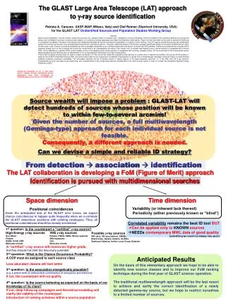
Can we afford to build an extremely large groundbased diffraction limited optical/IR telescope? Jim Oschmann Francois Rigaut Mike Sheehan Larry Stepp Matt MountainGemini Observatory
Can we afford to build an extremely large groundbased diffraction limited optical/IR telescope? Or can we afford ~ $1,000M Probably yes...
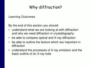
Framework for a credible Extremely Large/Maximum Aperture Telescope Concept Science Case Gallagher et al, Strom et al An adaptive optics solution Rigaut et al A telescope concept Mountain et al A viable instrument model Ramsay Howat et al
Spectroscopic Imaging at 10 milli-arcsecond resolution - using NGST as “finder scope” Simulated NGST K band image • Blue for z = 0 - 3 • Green for z = 3 - 5 • Red for z = 5 - 10 = 0.1 l 2K x 2K IFU 0.005” pixels 48 arcseconds
Modeled characteristics of 20m and 50m telescope Assumed point source size (mas) 20M 1.2mm 1.6mm 2.2mm 3.8mm 4.9mm 12mm 20mm (mas) 20 20 26 41 58 142 240 50M 1.2mm 1.6mm 2.2mm 3.8mm 4.9mm 12mm 20mm (mas) 10 10 10 17 23 57 94 h 70% 70% 50% 50% 50% 50% 50% Assumed detector characteristics 1mm < l < 5.5mm 5.5mm < l < 25mm Id Nr qe Id Nr qe 0.02 e/s 4e 80% 10 e/s 30e 40% (Gillett & Mountain, 1998)
Relative Gain of groundbased 20m and 50m telescopes compared to NGST Imaging Velocities ~30km/s Groundbased advantage NGST advantage
No correction (AO off) New Directions for Adaptive Optics ~ arcminute corrected FOV’s possible (Rigaut et al) • Numerical simulations • 5 guide stars & 5 Wavefront sensors • 2 mirrors • 8 turbulence layers • 40’’ Field of view • J band • Fully correctedPSF across full field of view
No correction (AO off) MCAO on New Directions for Adaptive Optics ~ arcminute corrected FOV’s possible (Rigaut et al) • Numerical simulations • 5 guide stars & 5 Wavefront sensors • 2 mirrors • 8 turbulence layers • 40’’ Field of view • J band • Fully correctedPSF across full field of view
No correction (AO off) MCAO on New Directions for Adaptive Optics ~ arcminute corrected FOV’s possible (Rigaut et al) • Numerical simulations • 5 guide stars & 5 Wavefront sensors • 2 mirrors • 8 turbulence layers • 40’’ Field of view • J band • Fully correctedPSF across full field of view Optical Performance - Strehl Ratio at 500nm across a 20” x 20” FOV (Ellerbroek,1994) Multiconjugate Adaptive Optics On Axis Edge FOV Corner FOV 0.942 0.953 0.955
4.2 x 10⁹ 18.5 mm pixels 1.2 m 1.2 m Instrumentation -- the next constraint? (Ramsay Howatt et al) R = 8,000 across J, H & K 2K x 2K IFU 0.005” pixels l 10 arcsec
6.7 X 10⁷ Pixels Instrumentation -- the next constraint? (Ramsay Howatt et al) R = 8,000 across J, H & K 2K x 2K IFU 0.005” pixels l 10 arcsec Lets not assume diffraction limited instruments for 30m ~ 100m telescopes will be small
A 400 year legacy of groundbased telescopes 0 The next step ? 50m telescope
0 Technology has made telescopes far more capable, and affordable
Technology has made telescopes far more capable, and affordable
Technology has made telescopes far more capable, and affordable
Optical Design • Requirements • 50m aperture • Science field of view 0.5 - 1.0 arcminutes • Useable field of view 1.0 - 2.0 arcminutes (for AO tomography) • Minimize number of elements (IR performance) • Aim for structural compactness • KISS
50m 2m diameter F/1 parabola M1, 2m diameter M2 Optical Design
~ 3m F/20 Cassegrain focus Optical Design
Cassegrain Instrument #2 ~ 3m Adaptive Optics Unit Cassegrain Instrument #1 F/20 Cassegrain focus Optical Design
1 arcminute FOV (Science Field) 0 arcsec 30 arcsec Optical Performance
0 arcsec. 30 arcsec. 60 arcsec. Guide star FOV Optical Performance
30 60 0 arcsec l/10 rms wavefront error 1 micron wavelength Optical Performance
F/1 Segmented Parabola 50m Segment testing (no null lenses) ~25m Primary Mirror Approach The volume of glass in a 50-mm thick 8-meter segment is 2.5 cubic meters. This volume is equivalent to a stack of 1.5-meter diameter boules 1.4 meters high.
Primary Mirror Approach Actively controlled polishing The sag of an 8-meter segment is only 80 mm Testing Ion Figuring Final Testing
Primary Mirror Support • To reduce mass, reduce mirror substrate thickness ~ 50mm (1/4 of Gemini, ESO-VLT) • Individual segments still have to be supported against self weight
Primary Mirror Support Gravitational print through requires between 120 - 450 support points for a 20 cm thick meniscus
Primary Mirror Support - continued • As self weight deflection a D4/t2,~8m diameter, 50mm segment will need ~ 1800 support points • How many active support points do we need to correct deformations due to wind and thermal gradients?
Primary Mirror Support - continued • As self weight deflection a D4/t2,~8m diameter, 50mm segment will need ~ 1800 support points • How many active support points do we need to correct deformations due to wind and thermal gradients? • Estimate 1 in 6, ~ 300/segment which implies > 10,000 actuators to actively support a 50m mirror
Does maintaining 10,000 actuators challenge the Quality Control Engineers? • What Mean Time Between Failures (MTBF) does this require? • Assume 95% up-time, over 356 x 12 hour nights • Assume unacceptable performance will occur when 5% of actuators fail • Assume it takes 1 hour to replace actuator, and that we can service 8 actuators a day, over 250 maintenance days • Therefore we can replace/service 2,000 actuators/year • MTBF required is 380,000 hours • Required service life of each actuators, assuming maintenance is 5 years
Challenges for the Structural Engineers ... • Telescope Optical Structure Requirements: • 50m surface must be held ~ l/10 against gravitational and wind loads • Relative pointing and tracking ~ 3 arcseconds rms • Absolute pointing/tracking provided by Star-tracker • Precision guiding/off-setting controlled by M4 and A&G/AO system • “Clean” top-end for IR emissivity, but rigid enough to launch 5 laser beacons • Challenges • 20mm mirror substrate still weighs ~ 110 kg/m2 (c.f ~ 75 kg/m2 for Gemini/Zeiss M2) • Mirror segments + cells could weigh 5.5 x 45 + 200 = 450 tonnes • Wind………….. • 10 m/s across 50m a lot of energy at ~ 0.2 Hz
Challenges for the Structural Engineers ... • Telescope Optical Structure Requirements: • 50m surface must be held ~ l/10 against gravitational and wind loads • Relative pointing and tracking ~ 3 arcseconds rms • Absolute pointing/tracking provided by Star-tracker • Precision guiding/off-setting controlled by M4 and A&G/AO system • “Clean” top-end for IR emissivity, but rigid enough to launch 5 laser beacons • Challenges • 20mm mirror substrate still weighs ~ 110 kg/m2 (c.f ~ 75 kg/m2 for Gemini/Zeiss M2) • Mirror segments + cells could weigh 5.5 x 45 + 200 = 450 tonnes • Wind………….. • 10 m/s across 50m a lot of energy at ~ 0.2 Hz
Resonant Frequencies of Large Telescopes Parabolic Reflector Antenna Systems Optics Systems (Laser/Infrared) Lowest Servo Resonant Frequency Frequency (Hz) 2Hz Telescope Aperture 50m
Mirror-to-cell actuators Integrated mirror/cell segment Large stroke actuators Mirror support truss with smart structure elements/active damping as needed Optical/Mechanical concept Three levels of figure control: • Each mirror segment • is controlled within an individual cell • Each cell is then controlled with respect to the primary mirror support structure • The support structure may have to use “smart structure” technology to maintain sufficient shape and/or damping for slewing/tracking
Concept Summary Optical support structure uses at least three levels of active control
Cassegrain Instrument #2 Adaptive Optics Unit Cassegrain Instrument #1 Concept Summary Optical support structure uses at least three levels of active control Collimated beam allows M3 & M4 to be tested independently and allows AO/instrument structure to be rigidly coupled to F/20 focus - insensitive to translation or rotation relative to 50m structure
Cassegrain Instrument #2 Adaptive Optics Unit Cassegrain Instrument #1 Concept Summary Optical support structure uses at least three levels of active control Collimated beam allows M3 & M4 to be tested independently and allows AO/instrument structure to be rigidly coupled to F/20 focus - insensitive to translation or rotation relative to 50m structure M2 easy to make/test - may need a little more rigidity….
75m 75m 150m 150m An Enclosure for 50m -- “how big?” • Restrict observing range to airmasses < 2.0 30 degrees • “Astro-dome” approach
75m 75m 150m 150m An Enclosure for 50m -- “how big?” • Restrict observing range to airmasses < 2.0 30 degrees • “Astro-dome” approach • Heretical proposition #1 - excavate • significantly lowers enclosure cost • further shields telescope from wind • reliant on AO to correct boundary layer
75m 75m 150m 150m An Enclosure for 50m -- “how big?” • Restrict observing range to airmasses < 2.0 30 degrees • “Astro-dome” approach • Heretical proposition #1 - excavate • significantly lowers enclosure cost • further shields telescope from wind • reliant on AO to correct boundary layer • Heretical proposition #2 - perhaps the wind characteristics of a site are now more important than the seeing characteristics
Framework for a credible Extremely Large/Maximum Aperture Telescope Concept Science Case An adaptive optics solution A telescope concept A viable instrument model
Image of a 21st Century Ground-Based Observatory -- 50m Class