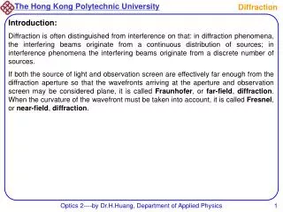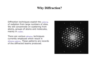
Why diffraction?
Why diffraction?. Learning Outcomes By the end of this section you should: understand what we are looking at with diffraction and why we need diffraction in crystallography be able to compare optical and X-ray diffraction be able to outline the factors which are important in diffraction

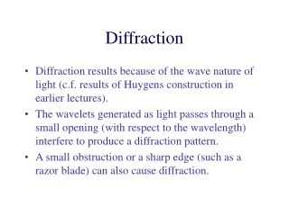
Why diffraction?
E N D
Presentation Transcript
Why diffraction? Learning Outcomes By the end of this section you should: • understand what we are looking at with diffraction and why we need diffraction in crystallography • be able to compare optical and X-ray diffraction • be able to outline the factors which are important in diffraction • understand the processes of X-ray emission and the basic outline of an X-ray tube
Characterisation of Solids What is it? • Powder • Single crystal • Glass/amorphous • Polymer • Inorganic/Organic • Composite material Insulin crystals, Nasa.gov
Characterisation of Solids What scale are we interested in? • Bulk/Macro – overall structure • Micro (microstructure) – grains, defects • Nano – crystal structure SiC screw disclocation, from http://focus.aps.org/story/v20/st3 Open porous structure in lava flow
Characterisation of Solids What part are we interested in? • Surface vs bulk - • Defects vs “perfection” ---semiconductors Properties? • Mechanical • Magnetic/electronic/ionic • Chemical (e.g. catalytic, pharmaceutical….) Obviously many techniques are required to fully characterise a material Silicon single crystal Graphite surface Pictures from http://materials.usask.ca/photos/
Single crystal Powder diffraction X-ray electron neutron “Perfect Solids” • Best-case scenario? “Perfect” crystalline solid. • Want to find the atom-level structure • Primary techniques: DIFFRACTION
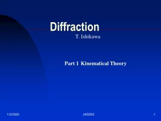
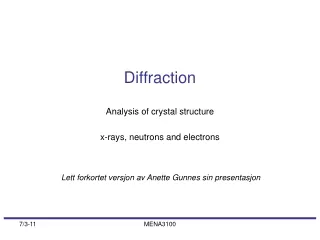
Revisiting Bragg 1912 - Friedrich & Knipping, under direction of Laue Extended by W. H. and W. L. Bragg (father and son) Based on existing optical techniques Max von Laue 1879 -1960 Nobel Prize 1914 “for his discovery of the diffraction of X-rays by crystals” W. H. Bragg 1862 -1942 W. L. Bragg 1890 -1971 Nobel Prize 1915 “for their services in the analysis of crystal structure by means of X-rays"
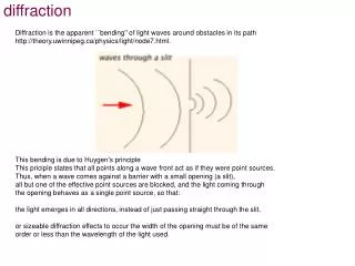
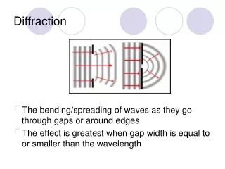
Optical grating – a 1d analogue Path difference XY between diffracted beams 1 and 2: sin = XY/a XY = a sin
Possible Combination of waves • Destructive: Waves combine and are exactly “out of phase” with each other – cancelling. = /2 • Constructive: Waves combine and are exactly “in phase” with each other – adding together to give maximum possible. = • Partial: Somewhere between the two.
Result for OPTICAL grating Path difference XY between diffracted beams 1 and 2: sin = XY/a • XY = a sin For constructive interference, we want XY to be a whole number of wavelengths So for this set-up, a sin = for first order diffraction
Result for OPTICAL grating What we see:
D L General Diffraction After the diffraction tan = D/L but if D<<L then we can write sin ~ D/L But a sin = So…. a ~ L/D
Summary of diffraction so far… • Diffraction side: a is related to Observation side: D is related to L • a sin = so sin = /a • This means that a must be > or else sin is > 1 • If a >> then sin 0 and we see nothing • D is related to 1/a, so the closer the slits, the further apart the diffraction lines. You can see this nicely in this applet: Diffraction Applet
Optical X-ray • With optical diffraction we can observe effects from a couple of slits • With X-rays, the interaction with matter is very weak – most pass straight through • Therefore we need many (100-1000s) of waves
na 0a D C B A Laue Equations – 3d • By analogy with the above: For constructive interference: (AB – CD) = a (cos na – cos 0a) = nx and for y & z b (cos nb – cos 0b) = ny c (cos nc – cos 0c) = nz
Laue equations – in reality • These work well and describe the interactions • Basic idea is still the constructive interference which occurs at an integer no. of wavelengths • However, not routinely used • Bragg’s law represents a simpler construct for everyday use! 2d sin = n Make sure you (PX3012) can derive this (Dr. Gibson’s lectures)
But WHY do we need diffraction? Why not just use a big microscope? • “Can’t” focus X-rays (yet?!!) Swift: - Instruments - The X-Ray Telescope • Electron microscope… not quite there yet, limited in application. HREM image of gold Delft University of Technology (2007)
Tilt your head… • If we draw the Bragg construction in the same way as the optical grating, we can clearly see that the diffracted angle is 2. The plane of “reflection” bisects this angle. • Thus we measure 2 in the experiment – next section… “Reflecting plane”
c = X-rays and solids X-rays - electromagnetic waves So X-ray photon has E = h X-ray wavelengths vary from .01 - 10Å; those used in crystallography have frequencies 2 - 6 x 10¹⁸ Hz Q. To what wavelength range does this frequency range correspond? max = 1.5 Å min = 0.5 Å
Energy and Wavelength Energy of photons usually measured in keV – why? (Å) Looking for wavelengths of the order of Å therefore need keV
X-ray emission Two processes lead to two forms of X-ray emission: • Electrons stopped by target; kinetic energy converted to X-rays • continuous spectrum of “white” radiation, with cut-off at short (according to h=½mv2) • Wavelength not characteristic of target • Incident electrons displace inner shell electrons, intershell electron transitions from outer shell to inner shell vacancy. • “line” spectra • Wavelength characteristic of target
X-ray spectrum Mixture of continuous and line
Characteristic wavelengths • Thus, each element (target) has a characteristic wavelength. For copper, the are: • CuK1 = 1.540 Å • CuK2 = 1.544 Å • CuK = 1.39 Å Typical emission spectrum
Energy transitions Many intershell transitions can occur - the common transitions encountered are: 2p (L) - 1s (K), known as the K line 3p (M) - 1s (K), known as the K line (in fact K is a close doublet, associated with the two spin states of 2p electrons)
Example Copper K X-rays have a wavelength of 1.54 Å and are produced when an electron falls from the L shell to a vacant site in the K shell of a copper atom. Calculate the difference in the energy levels between the K and L shells of copper. E = h = c/ = (3 x10⁸) / (1.54 x 10⁻¹⁰) = 1.95 x 10¹⁸ Hz E = h = 6.626 x 10-34x 1.95 x 1018 = 1.29 x 10⁻¹⁵ J ~ 8 keV ..and vice versa - each transition has its own wavelength.