Download
1 / 52
560 likes | 979 Vues
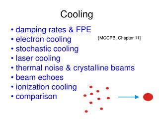
Cooling. damping rates & FPE electron cooling stochastic cooling laser cooling thermal noise & crystalline beams beam echoes ionization cooling comparison. [MCCPB, Chapter 11]. cooling: reduction of phase-space volume & increase in beam density via dissipative forces

E N D
Cooling • damping rates & FPE • electron cooling • stochastic cooling • laser cooling • thermal noise & crystalline beams • beam echoes • ionization cooling • comparison [MCCPB, Chapter 11]
cooling: reduction of phase-space volume & increase in beam density via dissipative forces e-/e+ storage rings: cooling from synchrotron radiation SR ‘damping rings’ for linear colliders; light sources electron cooling & stochastic cooling of hadron beams accumulate beams of rare particles (e.g., pbar), combat emittance growth due to scattering on internal target, produce high-quality beams two types of laser cooling:extremely coldion beams & ultra-low emittanceelectron beams ionization cooling for muon beams & muon collider
1. damping rates & Fokker-Planck equation dissipative force recall damping rate elementary calculation shows that damping rates in the 3 planes are related: W: rate of energy loss p: particle momentum in the case of synchrotron radiation this is called the ‘Robinson theorem”
mathematically cooling can be described by Fokker-Planck equation simple example f: distribution function “noise” cooling stationary solution with I0: final equilibrium emittance due to “noise” cooling does not produce smaller and smaller beams
2. electron cooling proposed in 1966 by Budker first experiments at NAP-M storage ring at INP in Novosibirsk where an antiproton beam was cooled by many orders of magnitude longitudinally and transversely drms~1.4x10⁻⁶, t~25 ms idea: hadron beam & accompanying electron beam exchange heat via Coulomb collisions e- temperature must be lower than hadron temperature easily fulfilled since
definition of temperature factors 2 or 3 in the literature equivalent definitions for e- beam for maximum Coulomb cross section average velocities of ions and e-should be the same
schematic of electron cooling for an ion storage ring velocity of cooled coasting beam equal to that of the e- beam as a result of the cooling useful tool for tuning the ion-beam energy; for bunched ion beam the rf frequency must be adjusted in order to match e- beam velocity
rough estimate of cooling force collision of two particles, single ion and single electron; reference frame where e- at rest before the collision split collision 2 steps: (1) approach, (2) separation; duration of either step Dt~r/u (=impact parameter / ion velocity) velocity after 1st step distance moved after 1st step collision of 1 ion and 1 electron during e- cooling
integrating over impact parameter r: expanding in Dr * with minimum impact parameter: classical head-on collision Debye shielding length
* averaging over the e- velocity distribution cooling force cooling rate transform to laboratory frame, obtain two factors g due to time dilation and Lorentz contraction cooling time if ion velocity is larger or smaller than rms e- velocity spread: ion velocity assuming Gaussian e- distribution
remarks: • large for large g • short if M small and Z high • ~ u3 for hot beam • independent of ion velocities and only dependent on e- temperature for cold beam typical parameters:
cooling force Fel=Mu/telin a ‘flattened’ e- beam as a function of ion velocity in units of rms e- velocity in beam frame ve,rms; dashed curves correspond to asymptotic formulae from previous page; difference between transverse and longitudinal plane is due longitudinal acceleration
two additional effects which reduce the cooling time: • acceleration of e- in longitudinal direction • e- velocity distribution is flattened in longitudinal direction • faster longitudinal damping 2.longitudinal magnetic field which is employed to guide and confine e- beam • e- cyclotron motion • decreases effective transverse temperature of e- beam • reduces cooling times to values below 0.1 s recombination due to e- capture also faster cooling is faster for highly charged ions for higher energies cooling becomes less efficient, rate scales as ~g2, also higher e- energy would be required
optical functions at the e- cooler & e- current for cold electron beam large value of b should give larger cooling rate however, for large b also beam size is larger and ion beam samples effect of nonlinear e- space-charge field intermediate b is optimum! but in reality saturation, again due to e- space charge also
for higher current Ie-, increase in ve,rms which degrades the cooling force optimum Ie-
already cooled longitudinal velocity vs. horizontal position of the electron and ion beams due to space charge the e- velocities lie on a parabola; the ion velocity varies linearly with a slope inversely proportional to the dispersion Dxat the cooler finite large area is due to betatron oscillations
e- cooling of high-energy beams? inefficient (?) high-energy high-current e- beam needed e- storage ring; radiation damping preserves e- emittance cooling section proposal: C. Rubbia, 1978 S.Y. Lee, P. Colestock, K.Y. Ng, 1997 proton or ion storage ring bucket spacing should be integer ratio other approach: RLA with energy recovery for RHIC upgrade, BNL-BINP collaboration
3. stochastic cooling off-axis particle gives signal of length Ts~1/(2 W) where W is bandwidth of cooling system smallest fraction of beam that can be observed: “sample” N: total no. beam particles T: revolution time idea: S. van der Meer, 1968 1975 first experimental demonstration at CERN 1977-83 cooling tests at CERN, FNAL. Novosibirsk, INS-Tokyo;…
test particle x, applied correction -lx sum over other particles in the ‘sample’ or gain ignore other particles and set g=1: more rigorously: U: “noise-to-signal” ratio “mixing term”
simplified: “const” ~ 1/10 in practice typical time: t~1 s for N~107 CERN AA: factor 3x10⁸ increase in phase-space density e- cooling works best for cold beams stochastic cooling works best for large (hot) beams (and small N) stochastic cooling for “halo cleaning” electron “core freezing”
stochastic cooling for bunched beams has not yet been demonstrated need to operate at frequencies well above bunch fall-off frequency ~bc/sz unexpectedly strong coherent signals were observed promising alternative: optical stochastic cooling at much higher frequencies and bandwidth
application of stochastic cooling formalism: emittance growth from LHC transverse damper (D. Boussard) noise to Schottky-signal ratio LSB ~ as quantization noise gn: “reduced” feedback gain “feedback via the beam” total tune spread ~2-3.5 times rms spread 10 bit +/- 10 s
4. laser cooling A) ion beams laser cooling in atomic traps well known 1981 P. Channel, application to storage rings exploits Doppler frequency shift in ion rest frame ion beam ions at different energy see different laser frequency selective interaction
photon absorption and emission during laser cooling at each absorption recoil is added to the ion momentum emission is isotropic and on average does not change the ion momentum
evolution of ion momentum distribution during laser cooling of a bunched ion beam
ions with transition A->B so that wAB=w’ will absorb photons recoil velocity spontaneous emission is isotropic upper level should have short decay time to avoid stimulated (non-isotropic) emission =1/t decay time ultimate temperature
example: 100 keV 7Li+ beam transition at 548.5 nm CW dye laser t~43 ns lifetime single absorption DE=12 meV few mW laser power, 5 mm spot 1.2x10⁷ s-1 or 15 absorptions over 2 m IR length or 0.2 eV/turn ultimate temperature ~12 meV laser cooling requires adequate energy levels & transitions in reach of tunable lasers; so far only 4 ion species: 7Li+, 9Be+, 24Mg+, 166Er+ demonstrated experimentally in TSR & ASTRID, drms<10-6 so far only longitudinal cooling, transverse cooling via coupling, e.g., with momentum dispersion at rf cavity, near linear resonance
B) electron beams V. Telnov, 1996 Z. Huang, R. Ruth, 1998 e- bunch in ring interacts on each turn with intense laser beam laser acts like wiggler magnet with peak field Ilaser: laser intensity Z0: vacuum impedance (377 W) total power radiated damping time
transverse emittance: usually from dispersion invariant H, but here 1/g opening angle dominates relation between photon energy and scattering angle where number of photons scattered into dw: integrating the scattered angle squared over w yields quantum excitation; balancing the result with damping gives the transverse emittance extremely small
momentum spread e.g., sd ~1%, large • increased momentum spread • widens beam size in arc, reduces intrabeam scattering confines space-charge tune shift • requires good chromatic correction & high-frequency rf system for short bunches
5. crystalline beams cold beams have unusual noise spectra ordinary beam Schottky noise interaction with beam environment: coherent frequency shift where ! Wn=ndw spread in revolution frequency
beam noise power becomes direct measure of beam temperature remarkable suppression of noise spectrum for cold beam first observed with an electron-cooled proton beam at NAP-M in Novosibirsk “crystalline beams” predicted/proposed/observed new state of matter to be reached by strong cooling particles ’lock’ into fixed positions
Hamiltonian in convenient coordinates inter-particle potential relativistic shear term - can render the Hamiltonian unbounded in the beam frame (accelerated frame of reference) this and the time-dependent focusing can melt the crystal • 2 conditions for crystal beams: • AG lattice, below transition (kinematically stable) • ring lattice periodicity larger than 2x maximum • betatron tune (no linear resonance between • crystal phonons and machine lattice periodicity)
low density: 1-D crystal when 2-D crystal in plane with weaker focusing still larger density 3-D crystal distance between nearest neighbors crystalline beams have been observed in the ESR and SIS rings in Darmstadt
6. beam echoes two independent pulse excitations later coherent signal grows out of a quiet beam slope + magnitude diffusion process beam temperature (e.g., Dp/p) analytical example in textbook dipole kick followed by quadrupole kick start with initial Gaussian distribution use action-angle coordinates compute time evolution with some approximations include tune shift with action (important)
two-particle model of signal recoherence after applying first a dipole kick and then a quadrupole kick, essential: tune change with amplitude
evolution of distribution function solve Vlasov equation OR exploit Liouville’s theorem tricks used: centroid displacement dipole kick
average displacement as a function of time following a dipole kick (G. Stupakov)
echo signal of the beam after a second (quadrupole) kick was applied (G. Stupakov); signal proportional to product of kicks
measurements of longitudinal echoes 2 rf kicks applied at frequencies f1 and f2; response is observed at difference frequency f1-f2 e.g. excitation at h=10, h=9 (harmonic number) -> echo at h=1 time of echo: time between excitations proportional to kick strength collision or diff. rate diffusion destroys reversibility of the decoherence determine n! TeV Acc. n~3x10⁻⁴ Hz measured techo: time from1st kick to centre of echo
at center of echo zero response ~ slope of distribution function shape of echo, e.g. spacing between two peaks, contains information on shape of distribution and on rms momentum spread allows detection of non-Gaussian distribution effect of longitudinal wake fields nonlinear momentum compaction factor L. Spentzouris, P. Colestock, ~1995
transverse echo after applying two dipole kicks (F. Ruggiero et al., 2000) time 0: large kick time t: small kick ~1/2 Dr’ (1/2 distance between filaments) time 2t: signal reappears
5s kick 0.25s kick <x>/s echo simulated echo signal for m=-2x10⁻⁴
echo? measurement at SPS: 0.9s kick followed by 0.2s kick simulation for the same parameters of experiment, detuning with amplitude estimated from decay time good agreement!
7. ionization cooling muon collider requires reduction in m phase-space volume by factor 106 proposed scheme: ionization cooling, similar to e- cooling where e- beam is replaced by solid material energy loss described by Bethe-Bloch formula I: average ionization energy density effect d~2 lng only longitudinal momentum is restored by rf transverse damping
transverse cooling: damping (energy loss & accleration) heating (multiple scattering) preferred: small beta function and large radiation length LR (low Z)
schematic of ionization cooling in the transverse phase space using a series of low-Z absorbers and re-acceleration