CHAPTER 8 Cooling System Operation and Diagnosis
1.11k likes | 1.91k Vues
CHAPTER 8 Cooling System Operation and Diagnosis. OBJECTIVES. After studying Chapter 8, the reader will be able to: Prepare for Engine Repair (A1) ASE certification test content area “D” (Lubrication and Cooling Systems Diagnosis and Repair). Describe how coolant flows through an engine.

CHAPTER 8 Cooling System Operation and Diagnosis
E N D
Presentation Transcript
CHAPTER 8 Cooling System Operation and Diagnosis
OBJECTIVES After studying Chapter 8, the reader will be able to: • Prepare for Engine Repair (A1) ASE certification test content area “D” (Lubrication and Cooling Systems Diagnosis and Repair). • Describe how coolant flows through an engine. • Discuss the operation of the thermostat. • Explain the purpose and function of the radiator pressure cap. • Describe the various types of antifreeze and how to recycle and discard used coolant. • Discuss how to diagnose cooling system problems.
Bar Bypass Cavitation Centrifugal pump Coolant recovery system Core tubes Ethylene glycol Fins Impeller Reverse cooling Scroll Silicone coupling Surge tank Thermostat Thermostatic spring KEY TERMS
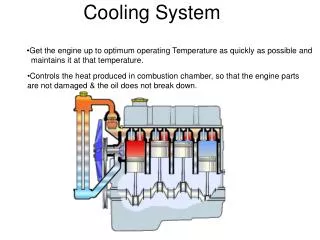
COOLING SYSTEM PURPOSE AND FUNCTION • Satisfactory cooling system operation depends on the design and operating conditions of the system. • The design is based on heat output of the engine, radiator size, type of coolant, size of water pump (coolant pump), type of fan, thermostat, and system pressure. • Unfortunately, the cooling system is usually neglected until there is a problem. • Proper routine maintenance can prevent problems.
COOLING SYSTEM PURPOSE AND FUNCTION • The cooling system must allow the engine to warm up to the required operating temperature as rapidly as possible and then maintain that temperature. • It must be able to do this when the outside air temperature is as low as 30°F (35°C) and as high as 110°F (45°C).
FIGURE 8–1 Typical combustion and exhaust temperatures. COOLING SYSTEM PURPOSE AND FUNCTION
Overheating Can Be Expensive • A faulty cooling system seems to be a major cause of engine failure. Engine rebuilders often have nightmares about seeing their rebuilt engine placed back in service in a vehicle with a clogged radiator. Most engine technicians routinely replace the water pump and all hoses after an engine overhaul or repair. The radiator should also be checked for leaks and proper flow whenever the engine is repaired or replaced. Overheating is one of the most common causes of engine failure.
LOW-TEMPERATURE ENGINE PROBLEMS • To reduce cold-engine problems and to help start engines in cold climates, most manufacturers offer block heaters as an option. • These block heaters are plugged into household current (110 volts AC) and the heating element warms the coolant.
Overheating Can Be Expensive • Many areas of the United States and Canada have exhaust emission testing. Hydrocarbon (HC) emissions are simply unburned gasoline. To help reduce HC emissions and be able to pass emission tests, be sure that the engine is at normal operating temperature. Vehicle manufacturers’ definition of “normal operating temperature” includes the following: • Upper radiator hose is hot and pressurized. • Electric cooling fan(s) cycles twice.
Overheating Can Be Expensive • Be sure that the engine is operating at normal operating temperature before testing for exhaust emissions. For best results, the vehicle should be driven about 20 miles (32 kilometers) to be certain that the catalytic converter and engine oil, as well as the coolant, are at normal temperature. This is particularly important in cold weather. Most drivers believe that their vehicle will “warm-up” if allowed to idle until heat starts flowing from the heater. The heat from the heater comes from the coolant. Most manufacturers recommend that idling be limited to a maximum of 5 minutes and that the vehicle should be warmed up by driving slowly after just a minute or two to allow the oil pressure to build.
HIGH-TEMPERATURE ENGINE PROBLEMS • High coolant temperatures raise the combustion temperatures to a point that may cause detonation and preignition to occur. • These are common forms of abnormal combustion. • If they are allowed to continue for any period of time, the engine will be damaged.
COOLING SYSTEM DESIGN • Coolant flows through the engine, where it picks up heat. • It then flows to the radiator, where the heat is given up to the outside air. • The coolant continually recirculates through the cooling system.
FIGURE 8–2 Coolant flow through a typical engine cooling system. COOLING SYSTEM DESIGN
FIGURE 8–3 Coolant circulates through the water jackets in the engine block and cylinder head. COOLING SYSTEM DESIGN
COOLING SYSTEM DESIGN • Its temperature rises as much as 15°F (8°C) as it goes through the engine; then it recools as it goes through the radiator. • The coolant flow rate may be as high as 1 gallon (4 liters) per minute for each horsepower the engine produces. • Hot coolant comes out of the thermostat housing on the top of the engine. • The engine coolant outlet is connected to the top of the radiator by the upper hose and clamps.
COOLING SYSTEM DESIGN • The coolant in the radiator is cooled by air flowing through the radiator. • As it cools, it moves from the top to the bottom of the radiator. • Cool coolant leaves the lower radiator area through an outlet and lower hose, going into the inlet side of the water pump, where it is recirculated through the engine.
THERMOSTAT TEMPERATURE CONTROL • There is a normal operating temperature range between lowtemperature and high-temperature extremes. • The thermostat controls the minimum normal temperature. • The thermostat is a temperature-controlled valve placed at the engine coolant outlet. • An encapsulated, wax-based, plastic-pellet heat sensor is located on the engine side of the thermostatic valve. • As the engine warms, heat swells the heat sensor.
FIGURE 8–4 A cross-section of a typical wax-actuated thermostat showing the position of the wax pellet and spring. THERMOSTAT TEMPERATURE CONTROL
FIGURE 8–5 (a) When the engine is cold, the coolant flows through the bypass. (b) When the thermostat opens, the coolant can flow to the radiator. THERMOSTAT TEMPERATURE CONTROL • A mechanical link, connected to the heat sensor, opens the thermostat valve. • As the thermostat begins to open, it allows some coolant to flow to the radiator, where it is cooled.
FIGURE 8–6 A thermostat stuck in the open position caused the engine to operate too cold. The vehicle failed an exhaust emission test because of this defect. If a thermostat is stuck closed, this can cause the engine to overheat. THERMOSTAT TEMPERATURE CONTROL
Do Not Take Out the Thermostat! • If overheating is a problem, removing the thermostat will usually not solve the problem. Remember, the thermostat controls the temperature of the engine coolant by opening at a certain temperature and closing when the temperature falls below the minimum rated temperature of the thermostat. If overheating occurs, two basic problems could be the cause: • The engine is producing too much heat for the cooling system to handle. • The cooling system has a malfunction or defect that prevents it from getting rid of its heat.
THERMOSTAT TEMPERATURE CONTROLBYPASS • A bypass around the closed thermostat allows a small part of the coolant to circulate within the engine during warm-up. • It is a small passage that leads from the engine side of the thermostat to the inlet side of the water pump. • It allows some coolant to bypass the thermostat even when the thermostat is open. • The bypass may be cast or drilled into the engine and pump parts.
FIGURE 8–7 This Internal bypass passage in the thermostat housing directs cold coolant to the water pump. THERMOSTAT TEMPERATURE CONTROLBYPASS
FIGURE 8–8 A cutaway of a small block Chevrolet V-8 showing the passage from the cylinder head through the front of the intake manifold to the thermostat. THERMOSTAT TEMPERATURE CONTROLBYPASS
TESTING THE THERMOSTAT • There are three basic methods that can be used to check the operation of the thermostat. • Hot-water method • Infrared pyrometer method • Scan tool method
FIGURE 8–9 Setup used to check the opening temperature of a thermostat. TESTING THE THERMOSTAT
THERMOSTAT REPLACEMENT • An overheating engine may result from a faulty thermostat. An engine that does not get warm enough always indicates a faulty thermostat. • To replace the thermostat, coolant will have to be drained from the radiator drain petcock to lower the coolant level below the thermostat. • It is not necessary to completely drain the system. • The upper hose should be removed from the thermostat housing neck; then the housing must be removed to expose the thermostat.
FIGURE 8–10 Some thermostats are an integral part of the housing. This thermostat and radiator hose housing is serviced as an assembly. Some thermostats simply snap into the engine radiator fill tube underneath the pressure cap. THERMOSTAT REPLACEMENT
ANTIFREEZE/COOLANT • Coolant is a mixture of antifreeze and water. • Water is able to absorb more heat per gallon than any other liquid coolant. • Under standard conditions, water boils at 212°F (100°C) and freezes at 32°F (0°C). • When water freezes, it increases in volume about 9%. • The expansion of the freezing water can easily crack engine blocks, cylinder heads, and radiators. • All manufacturers recommend the use of ethylene glycol-based antifreeze mixtures for protection against this problem.
FIGURE 8–11 Graph showing the relationship of the freezing point of the coolant to the percentage of antifreeze used in the coolant. ANTIFREEZE/COOLANT
FIGURE 8–12 Graph showing how the boiling point of the coolant increases as the percentage of antifreeze in the coolant increases. ANTIFREEZE/COOLANT
What Is “Pet Friendly” Coolant? • Similar to ethylene glycol, propylene glycol is a type of coolant that is less harmful to pets and animals because it is not sweet tasting, although it is still harmful if swallowed. This type of coolant should not be mixed with ethylene glycol coolant.
If 50% Is Good, 100% Must Be Better • A vehicle owner said that the cooling system of his vehicle would never freeze or rust. He said that he used 100% antifreeze (ethylene glycol) instead of a 50/50 mixture with water. • However, after the temperature dropped to 20°F (29°C), the radiator froze and cracked. (Pure antifreeze freezes at about 0°F [18°C]). After thawing, the radiator had to be repaired. The owner was lucky that the engine block did not also crack.
If 50% Is Good, 100% Must Be Better • For best freeze protection with good heat transfer, use a 50/50 mixture of antifreeze and water. A 50/50 mixture of antifreeze and water is the best compromise between temperature protection and the heat transfer that is necessary for cooling system operation. Do not exceed 70% antifreeze (30% water). As the percentage of antifreeze increases, the boiling temperature increases, and freezing protection increases (up to 70% antifreeze), but the heat transfer performance of the mixture decreases.
ANTIFREEZE CAN FREEZE • An antifreeze and water mixture is an example wherein the freezing point differs from the freezing point of either pure antifreeze or pure water. • Depending on the exact percentage of water used, antifreeze, as sold in containers, freezes between 8°F and 8°F (13°C and 22°C). • Therefore, it is easiest just to remember that most antifreeze freezes at about 0°F (18°C).
HYDROMETER TESTING • Coolant can be checked using a coolant hydrometer. • The hydrometer measures the density of the coolant. • The higher the density, the more concentration of antifreeze in the water. • Most coolant hydrometers read the freezing point and boiling point of the coolant.
FIGURE 8–13 Checking the freezing and boiling protection levels of the coolant using a hydrometer. HYDROMETER TESTING
RECYCLING COOLANT • Coolant (antifreeze and water) should be recycled. • Used coolant may contain heavy metals, such as lead, aluminum, and iron, which are absorbed by the coolant during its use in the engine. • Recycle machines filter out these metals and dirt and reinstall the depleted additives. • The recycled coolant, restored to be like new, can be reinstalled into the vehicle.
Ignore the Windchill Factor • The windchill factor is a temperature that combines the actual temperature and the wind speed to determine the overall heat loss effect on exposed skin. Because it is the heat loss factor for exposed skin, the windchill temperature is not to be considered when determining antifreeze protection levels. • Although moving air does make it feel colder, the actual temperature is not changed by the wind and the engine coolant will not be affected by the windchill. Not convinced? Try this. Place a thermometer in a room and wait until a stable reading is obtained. Now turn on a fan and have the air blow across the thermometer. The temperature will not change.
DISPOSING OF USED COOLANT • Used coolant drained from vehicles can usually be disposed of by combining it with used engine oil. • The equipment used for recycling the used engine oil can easily separate the coolant from the waste oil. • Check with recycling companies authorized by local or state governments for the exact method recommended for disposal in your area.
RADIATOR DESIGN AND FUNCTION • Two types of radiator cores are in common use in domestic vehicles—the serpentine fin core and the plate fin core. • In each of these types the coolant flows through oval-shaped core tubes. • Heat is transferred through the tube wall and soldered joint to fins. • The fins are exposed to airflow, which removes heat from the radiator and carries it away.
FIGURE 8–14 The tubes and fins of the radiator core. RADIATOR DESIGN AND FUNCTION
FIGURE 8–15 A radiator may be either a down-flow or a cross-flow type. RADIATOR DESIGN AND FUNCTION
FIGURE 8–16 Cutaway of a typical radiator showing restriction of tubes. Changing antifreeze frequently helps prevent this type of problem. RADIATOR DESIGN AND FUNCTION
FIGURE 8–17 Many vehicles equipped with an automatic transmission use a transmission fluid cooler installed in one of the radiator tanks. RADIATOR DESIGN AND FUNCTION
PRESSURE CAP • The filler neck is fitted with a pressure cap. • The cap has a spring-loaded valve that closes the cooling system vent. • This causes cooling pressure to build up to the pressure setting of the cap. • At this point, the valve will release the excess pressure to prevent system damage.
FIGURE 8–18 The pressure valve maintains the system pressure and allows excess pressure to vent. The vacuum valve allows coolant to return to the system from the recovery tank. PRESSURE CAP
Working Better Under Pressure • A problem that sometimes occurs with a highpressure cooling system involves the water pump. For the pump to function, the inlet side of the pump must have a lower pressure than its outlet side. If inlet pressure is lowered too much, the coolant at the pump inlet can boil, producing vapor. The pump will then spin the coolant vapors and not pump coolant. This condition is called pump cavitation. Therefore, a radiator cap could be the cause of an overheating problem. A pump will not pump enough coolant if not kept under the proper pressure for preventing vaporization of the coolant.
SURGE TANK • Some vehicles use a surge tank, which is located at the highest level of the cooling system and holds about 1 quart (1 liter) of coolant. • A hose attaches to the bottom of the surge tank to the inlet side of the water pump. • A smaller bleed hose attaches to the side of the surge tank to the highest point of the radiator. • The bleed line allows some coolant circulation through the surge tank, and air in the system will rise below the radiator cap and be forced from the system if the pressure in the system exceeds the rating of the radiator cap.
FIGURE 8–19 Some vehicles use a surge tank, which is located at the highest level of the cooling system, with a radiator cap. SURGE TANK