Download
1 / 32
320 likes | 481 Vues
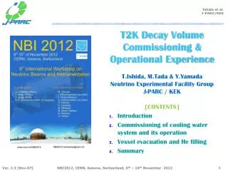
T2K Decay Volume Commissioning & Operational Experience T.Ishida , M.Tada & Y.Yamada Neutrino Experimental Facility Group J-PARC / KEK [CONTENTS]. Introduction Commissioning of cooling water system and its operation Vessel evacuation and He filling Summary . 1. Introduction.

E N D
T2K Decay VolumeCommissioning & Operational ExperienceT.Ishida, M.Tada & Y.YamadaNeutrino Experimental Facility GroupJ-PARC / KEK[CONTENTS] • Introduction • Commissioning of cooling water system and its operation • Vessel evacuation and He filling • Summary
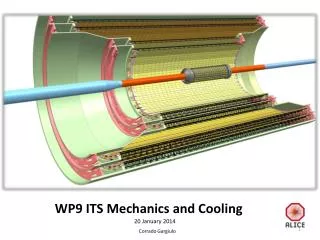
Neutrino Secondary Beam-line Vessel filled w 1atm. He gas L=~110m,V=1,600m3 • Target Station(TS), Decay Volume(DV), & Beam Dump(BD) • TS: He-cooled graphite target, 3 magnetic horns, remote maintenance • DV: 94m-long tunnel with rectangular cross section • BD: hadron absorber made of large graphite blocks, surrounding iron shields • All the apparatus are enclosed in a gigantic vacuum/helium vessel, made of carbon steel plates. • He atmosphere aims to prevent nitrogen oxide (NOx) production / oxidization of apparatus. • Iron plates of the vessel are cooled by water circuits. • Maintenance is not possible after beam operation due to irradiation. • Radiation shielding / cooling capacity were designed to accept up to ~4MW beam (w/o safety margin). Target Station Muon pit Beam Transport From RCS to MLF Beam Dump Decay Volume OA2o OA2.5o OA3o 6m-thick concrete wall
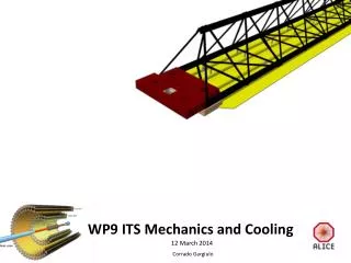
Target Station (TS) • Horns / a baffle are supported from the wall of vessel by support modules. • Apparatus on the beam-line are highly irradiated after beam. Remote maintenance is key issue. Large flange, sealed with Al plates, t= 120mm Service Pit 1.0m Concrete blocks Beam window Ti-alloy Water-cooled iron cast blocks 29pcs. total 470t 2.3m Horn-3 Horn-2 10.6m Horn-1 Beam Support Module Target OTR Baffle Graphite Collimator DV collimator 15.0m Disassemble @ maintenance area
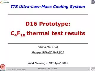
Horns in the TS Vessel Horn-2 [downstream] Horn-3 [upstream] • Integrated # of pulses (~Run-3): 7~8M • Current stability ~2% remote Connections Horn ~ support Clearances ~30mm Supply helium ducts covering bus-bars Flow rate (entire He vessel): 2,400m3/h Water cooling: Heat load @ 750kW at most ~45 oC • Alignment precision of horns : • 0.3mm(x), 1mm(y), 1mm (z-beam) Photos on Sep., 2009 (before Physics Run)
Decay Volume • Water circuits are separated to upstream and downstream. • Each composed of 20 circuits – 40 water channels. 1.4m • entrance • downstreamend 1.7m “Plate Coil” Water cooling channel 2009/9/26 5.1m U-shaped pipe connection (25A) 3.2mm 3.0m 2009/2/27 16mm
Plumbing at μPit [West side wall] • Control water flow of 260water channels (130 circuits), ~500 Valves (25A) • Though it is designed to use half of the circuits for 750kW beam, we forced to use all channels with low flow rate. • It may cause troubles for carbon steel, if we remove water from the channels. • To Decay Volume • (downstream) TP -5.1m • To BD • Upstream shield • To Absorber • cooling modules TP -12m • Supply • header • Return • header
Cooling Water System at NU3[downstream DV + BD] • Industrial • water • supply • Purified • water • supply • Outside • yard • [GL] • Similar system at TS • Tertiary • Cooling • towers • N2 gas • supply • for ET • Expansion • tank • Hot • machine • room • [1F] • Heat • exch. • Secondary • Degasifier • Hollow fiber membrane • [+ 0.5um Pre-filter] • Exp. tank • [Water supplier] • [B1F+4.5m stand] • Centrifugal • pumps • Ion-exchange resins • [+ 0.5um Pre-filter] • Superhot • machine • room • [B1F] • HEX • Temporary pump + • filter system • for flushing • [later moved to B1F] • Primary • (Activated) • DV/BD • Muon pit • [B2F] • Header
Water System Commissioning (Mar.2009) • Initial flushing with industrial water (Mar.12) • Remove dusts/rusts AFAP by independent circuit with a pump and filters (with purified water) • ASA the water becomes clean, start operation of the main water system (Apr.3) • Switch on degasifier to stop corrosion (Apr.6) • Switch on ion exchange resin system (Apr.14) Pump Apr. 1 Bag-type filter/strainer (5um) Mar. 13 Cooling water system is running continuously in basis, except for the shutdown due to the earthquake (Mar.~Jun. 2011) and repair works (Jun.~Sep.2012). Serial Pleats filters(0.5um) B2F
Water System Operation • Water is clean and transparent. No corrosion observed so far. • It may owe to the vacuum degasifier: dissolved oxygen O(ppm)→1~10ppb • No corrosion even after the ~3month shutdown by the earthquake • Problem: inside of circuit is coated by black color. • We were forced to curve impellers/casings of the centrifugal pumps. • We stopped to use ion exchanging resins since Sep.2009 • Resistivity: In 1.2 /Out 18 MΩ・cm(Apr.14,’09) Out 13 MΩ・cm(Sep.14’09) • They may just adsorb Fe ions, and thus erode inside of carbon steel pipes. Chemical solutions in the primary cooling water (with resin operated): mostly powder(solid), not solution. May 1,’09 Aug.20’09 0.2mg / litter 2g-Fe / 10m3 Flow meter of degasifier (Jul. 2009) Strainer mesh (Sep. 2012)
Pump Repair (Curve Impeller/Casing)[Dec.26-27, 2010 for pump-1]
Radiation Issues • Radioactive nuclei in the primary cooling water • Run-3: Mar.~Jun.9, 2012 (4month), 1.6x10²⁰pot, -190kW • Measured on Jun.13(+4d). Only 3H is beyond limit for disposal. • So far daughters of Fe is not serious problems. • Residual dose in the B1 super-hot machine room • Jun.11, 2012 (+2days after beam) • Pre-filter of degasifier: 600uSv/h Degasifier itself (Hollow fiber membrane Module x 6) : 20~45uSv/h • The 0.3um pleats filter seems to be effective to adsorb 7Be • On Sep.2012, we have duplicated the pre-filter and moved into a compartment of iron shields for resins (not used) DP tank:1 Resins(not used) PostFilter:10 PreFilter:60 600uSv/h 20-45 HEX:28 55(IC) Pump:2(IC)
Degasifier • Hollow fiber membrane • SEPHAREL EF-040P x 6 • 0.3um pleats pre-filters moved into compartment of resins • (Sep. 2012)
How to detect water leak ? • Leak sensors installed at a drain port of the Helium vessel. • Total amount of water-supply to the expansion tank is monitored. • We found 20 litter/day (~1 water drop/sec) water leak at one drain valve. • This will also be a good way to identify bad water circuits. Nov.14, 2009 Litters supplied in total
Vessel Evacuation / Leak Test • Evacuation test (Feb. 3~18,’09): • The vacuum saturated w ~50Pa (Spec value: <13Pa) • Leak found by helium leak detector at connection of BD/DV, where very complicated welding pattern was used. • Repaired, but no time to continue helium leak tests. He-spraying pipes pre-installed in dump pit for further tests. • Ceiling of dumppit closed on Feb.18th, 2009. Feb.15 2009 3 Mechanical-booster pumps @ TS B1 stand BD-top BD-upstr. (top) BD-side DV BD-upstr. (side)
Evacuation for He filling[Oct.2009] • 1st experience to evacuate with full-setup • All horns & iron/concrete shield blocks, feed-through / piping. • Vacuum saturated at 80~90 Pa in a week. • The leak at BD was NOT fixed. At most 10-2~10-1 Pa・m3/s=1~10ppmO2/d • Aggravation rate was 43~46 Pa/h: 20 Pa・m3/s Restart evacuation (16th 17:30~) 730Pa8:05 Rate= 46.0Pa/h (ave 13.8hrs) 2nd trial in Oct.’09 Separate Horns (17th 10:00)@240Pa He leak tests btw Horn & Vessel (put He gas in horns) 260Pa 94Pa 18:15 91Pa Pump stopped by mistake 10:40 81 Pa 86 Pa
Test Outgas Measurements 60 kg scale dM =1g 495Φx1,000L V=0.192 m3 S=1.94 m2 • BG 12Pa/h =3.3x10⁻⁴ Pa・m3/s/m2→ Vessel (1,700m2) 0.6 Pa・m3/s • Block 47(-12)Pa/h = 1.0x10⁻² Pa・m3/s/m2→ Shield(240m2) 3 Pa・m3/s • The values are still not consistent to 20 Pa・m3/s, but maybe comparable. Cf. Block weight: 0.023%/d →Shield(130t) 45 Pa・m3/s (assume all vapors remain) Block w paint V=6e-3 m3 13 kg Reduced -3g /day by evacuation Pump N2 gas for purge
Helium gas filling (Oct.29, 2009) • Filling was going very smoothly, finished in 2 hrs • An oxygen content meter and a dew point meter were set up in the drain pit of the mupit (now at B1F)
Oxygen Content / Dew point • Oxygen raised + 10ppm / 1day, but we notified • Positive correlation with atmospheric pressure • The raise stopped after adding +1kPa of more helium. • In later fillings we succeeded to keep vessel under 100ppm of oxygen • Dew point > 20 degC, almost saturated. DewP. 170 ppm Oxygen Atm. pressure He pressure +10 hPa 1030hPa 110ppm 1010hPa 130ppm 10/31 11/4
Reduce HTO during maintenance • After Run-2 (1.1x10²⁰pot, vessel was evacuated and air was filled (apr.27-28, 2011). After a month, HTO raised up to ~1Bq/cc • Cf. Limit to work (J-PARC): 500mBq/cc (16uSv/h internal exposure) • Cf. Limit for exhaust (J-PARC): 5mBq/cc in 3 month average. (X500 diluted.) • Before opening vessel, we send dried air (30m3/h) from NU3. • During maintenance, vessel air is sucked (28m3/h) to NU3. May 26, 2011 Room-Gas Monitor (Affected by Rn) 1.33 Bq/cc 1d 0.86 Bq/cc 2d June 16, 2011 0.55 Bq/cc 0.25 Bq/cc 0.64 Bq/cc 5d 0.21 Bq/cc 4d 0.38 Bq/cc 0.24 Bq/cc Ready to open vessel Sampled gas measurements 710 mBq/cc →270 mBq/cc 360 mBq/cc →185 mBq/cc ? mBq/cc →136 mBq/cc 1000 mBq/cc →490 mBq/cc
Dry air supplier at NU3 Water/Mist filters compressor He Vessel F • ~500ℓ/min, dew point < -10deg refrigerated dryer Hollow fiber membrane Hollow Fiber Membrane Dryer 3H monitor 194mBq/cc 48mBq/cc DewP +16℃ Refrigerated dryer 7/8 7/11 Dry air -5℃
Vessel Exhaust Line at NU3 HEPA filter Water separator To HEPAfilter filter ~470ℓ/min 680m3/day He Vessel Pump F Exhaust From Vessel Flow meter Spec: 876ℓ/min 3H monitor Pre filter Water separator Sample port 3H monitor
4. Summary • The T2K secondary beam-line is enclosed in a giant vacuum vessel, made of carbon steel, cooled by water, and filled with 1atm. Helium. • It is the first experience for our community, how to operate such a delicate, and possibly fragile, system. • Commissioning & operation of water circulation system is reviewed. • Water is clean enough so far, and no serious corrosion observed. It may thanks to the vacuum degasifier. • Whole the water lines are filled with water: it will double the radiation waste water: Desirable (but not essential) to study how to make half of pipes empty without damaging carbon steel. • Radioactive nuclei in the primary water: 3H production is only deal. Fe daughters are few.
Summary (Cont.d) • Vessel evacuation / He gas filling • Oxygen contamination of 10ppm/day was observed at commissioning • Consistent to the He leak test result at the BD pit (10-1 Pa・m3/s) • Air contamination can be suppressed by keeping vessel pressure slightly higher than atmospheric pressure. • Established the way to keep oxygen under requirement (~100ppm) • Dew point in the vessel > 20 deg.C, almost saturated. • The rate of the observed pressure rise (20 Pa・m3/s) may be caused by the water vapor from concrete blocks in the vessel. • He purification system (molecular sieve / cold trap ) is desirable to prevent 3H production. • Decay volume / beam dump after the earthquake • During 2011 shutdown: Inspection by Web-camera + LED • During 2012 shutdown: Expansion joint was repaired, whole flexible tubes replaced. • Entire system now running for Run-4 !
Visual Inspection of DV/BD[Summer, 2011] 36W LED, 3,600lm illuminating angle10deg MOS sensor, min.illuminance=0.5lx X36 (18x2EX) optical zoom lx
Vessel He contaminated by air[2012 March.] • Helium was contaminated by air ~2.5% (0.5% O2) • Small amount of NOX can be produced. • We will replace He anyway this summer to dilute 3H. Thin Pipe was broken (~Mar.9) Due to vibration of the Newly introduced Metal bellows pump Support and flexible tube is introduced To absorb vibration.
He Vessel Leak • It may be the reason of bad OTR image…