COOLING SYSTEM OPERATION AND DIAGNOSIS
560 likes | 796 Vues
21. COOLING SYSTEM OPERATION AND DIAGNOSIS. Figure 21-1 Typical combustion and exhaust temperatures.

COOLING SYSTEM OPERATION AND DIAGNOSIS
E N D
Presentation Transcript
21 COOLING SYSTEM OPERATION AND DIAGNOSIS
TECH TIP: Overheating Can Be Expensive A faulty cooling system seems to be a major cause of engine failure. Engine rebuilders often have nightmares about seeing their rebuilt engine placed back in service in a vehicle with a clogged radiator. Most engine technicians routinely replace the water pump and all hoses after an engine overhaul or repair. The radiator should also be checked for leaks and proper flow whenever the engine is repaired or replaced. Overheating is one of the most common causes of engine failure.
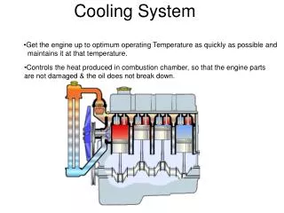
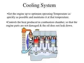
Figure 21-2 Coolant circulates through the water jackets in the engine block and cylinder head.
Figure 21-3 Coolant flow through a typical engine cooling system.
Figure 21-4 A cross section of a typical wax-actuated thermostat showing the position of the wax pellet and spring.
Figure 21-5 (a) When the engine is cold, the coolant flows through the bypass.
Figure 21-5 (b) When the thermostat opens, the coolant can flow to the radiator.
Chart 21-1 The temperature of the coolant depends on the rating of the thermostat.
Figure 21-6 A thermostat stuck in the open position caused the engine to operate too cold. If a thermostat is stuck closed, this can cause the engine to overheat.
Figure 21-7 This internal bypass passage in the thermostat housing directs cold coolant to the water pump.
Figure 21-8 A cutaway of a small block Chevrolet V-8 showing the passage from the cylinder head through the front of the intake manifold to the thermostat.
TECH TIP: Do Not Take Out the Thermostat! Some vehicle owners and technicians remove the thermostat in the cooling system to “cure” an overheating problem. In some cases, removing the thermostat can cause overheating rather than stop it. This is true for three reasons. 1. Without a thermostat the coolant can flow more quickly through the radiator. The thermostat adds some restriction to the coolant flow, and therefore keeps the coolant in the radiator longer. This also allows additional time for the heat transfer between the hot engine parts and the coolant. The presence of the thermostat thus ensures a greater reduction in the coolant temperature before it returns to the engine. 2. Heat transfer is greater with a greater difference between the coolant temperature and air temperature. Therefore, when coolant flow rate is increased (no thermostat), the temperature difference is reduced. 3. Without the restriction of the thermostat, much of the coolant flow often bypasses the radiator entirely and returns directly to the engine. If overheating is a problem, removing the thermostat will usually not solve the problem. Remember, the thermostat controls the temperature of the engine coolant by opening at a certain temperature and closing when the temperature falls below the minimum rated temperature of the thermostat.
Figure 21-9 Checking the opening temperature of a thermostat.
Figure 21-10 Some thermostats are an integral part of the housing. This thermostat and radiator hose housing is serviced as an assembly. Some thermostats snap into the engine radiator fill tube underneath the pressure cap.
Figure 21-12 (a) A radiator may be either a down-flow or a crossflow type.
Figure 21-12 (b) A radiator may be either a down-flow or a crossflow type.
Figure 21-13 Many vehicles equipped with an automatic transmission use a transmission fluid cooler installed in one of the radiator tanks.
TECH TIP: Working Better Under Pressure A problem that sometimes occurs with a high-pressure cooling system involves the water pump. For the pump to function, the inlet side of the pump must have a lower pressure than its outlet side. If inlet pressure is lowered too much, the coolant at the pump inlet can boil, producing vapor. The pump will then spin the coolant vapors and not pump coolant. This condition is called pump cavitation. Therefore, a radiator cap could be the cause of an overheating problem. A pump will not pump enough coolant if not kept under the proper pressure for preventing vaporization of the coolant.
Figure 21-14 The pressure valve maintains the system pressure and allows excess pressure to vent. The vacuum valve allows coolant to return to the system from the recovery tank.
Chart 21-2 Comparison showing the metric pressure as shown on the top of the cap to pounds per square inch (PSI).
Figure 21-15 The level in the coolant recovery system raises and lowers with engine temperature.
Figure 21-16 Some vehicles use a surge tank, which is located at the highest level of the cooling system, with a radiator cap.
REAL WORLD FIX: The Collapsed Radiator Hose Story An automotive student asked the automotive instructor what brand of radiator hose is the best. Not knowing exactly what to say, the instructor asked if there was a problem with the brand hose used. The student had tried three brands and all of them collapsed when the engine cooled. The instructor then explained that the vehicle needed a new pressure cap and not a new upper radiator hose. The student thought that because the lower hose did not collapse that the problem had to be a fault with the hose. The instructor then explained that the lower radiator hose has a spring inside to keep the lower hose from collapsing due to the lower pressure created at the inlet to the water pump. The radiator cap was replaced and the upper radiator hose did not collapse when the engine cooled.
Figure 21-17 Coolant flow through the impeller and scroll of a coolant pump for a V-type engine.
Figure 21-18 A demonstration engine running on a stand, showing the amount of coolant flow that actually occurs through the cooling system.
FREQUENTLY ASKED QUESTION: How Much Coolant Can a Water Pump Move? A typical water pump can move a maximum of about 7,500 gallons (28,000 liters) of coolant per hour, or recirculate the coolant in the engine over 20 times per minute. This means that a water pump could be used to empty a typical private swimming pool in an hour! The slower the engine speed, the less power is consumed by the water pump. However, even at 35 mph (56 km/h), the typical water pump still moves about 2,000 gallons (7,500 liters) per hour or 0.5 gallon (2 liters) per second! - SEE FIGURE 21–18 .
Figure 21-19 This severely corroded water pump could not circulate enough coolant to keep the engine cool. As a result, the engine overheated and blew a head gasket.
Figure 21-20 The bleed weep hole in the water pump allows coolant to leak out of the pump and not be forced into the bearing. If the bearing failed, more serious damage could result.
Figure 21-21 A cutaway of a typical water pump showing the long bearing assembly and the seal. The weep hole is located between the seal and the bearing. If the seal fails, then coolant flows out of the weep hole to prevent the coolant from damaging the bearing.
TECH TIP: Release the Belt Tension Before Checking a Water Pump The technician should release water pump belt tension before checking for water pump bearing looseness. To test a water pump bearing, it is normal to check the fan for movement; however, if the drive belt is tight, any looseness in the bearing will not be felt.
Figure 21-22 A Chevrolet V-8 block that shows the large coolant holes and the smaller gas vent or bleed holes that must match the head gasket when the engine is assembled.
Figure 21-23 A typical electric cooling fan assembly showing the radiator and related components.
WARNING: Some electric cooling fans can come on after the engine is off without warning. Always keep hands and fingers away from the cooling fan blades unless the electrical connector has been disconnected to prevent the fan from coming on. Always follow all warnings and cautions.
Figure 21-24 A typical engine-driven thermostatic spring cooling fan.
TECH TIP: Be Sure to Always Use a Fan Shroud A fan shroud forces the fan to draw air through the radiator. If a fan shroud is not used, then air is drawn from around the fan and will reduce the airflow through the radiator. Many overheating problems are a result of not replacing the factory shroud after engine work or body repair work to the front of the vehicle.
Figure 21-25 A typical heater core installed in a heating, ventilation, and air-conditioning (HVAC) housing assembly.
Figure 21-26 A heavily corroded radiator from a vehicle that was overheating. A visual inspection discovered that the corrosion had eaten away many of the cooling fins, yet did not leak. This radiator was replaced and it solved the overheating problem.
Figure 21-27 Pressure testing the cooling system. A typical handoperated pressure tester applies pressure equal to the radiator cap pressure. The pressure should hold; if it drops, this indicates a leak somewhere in the cooling system. An adapter is used to attach the pump to the cap to determine if the radiator can hold pressure, and release it when pressure rises above its maximum rated pressure setting.
Figure 21-28 The pressure cap should be checked for proper operation using a pressure tester as part of the cooling system diagnosis.
Figure 21-29 Use dye specifically made for coolant when checking for leaks using a black light.
Figure 21-30 When an engine overheats, often the coolant overflow container boils.
REAL WORLD FIX: Highway Overheating A vehicle owner complained of an overheating vehicle, but the problem occurred only while driving at highway speeds. The vehicle, equipped with a 4-cylinder engine, would run in a perfectly normal manner in city driving situations. The technician flushed the cooling system and replaced the radiator cap and the water pump, thinking that restricted coolant flow was the cause of the problem. Further testing revealed coolant spray out of one cylinder when the engine was turned over by the starter with the spark plugs removed. A new head gasket solved the problem. Obviously, the head gasket leak was not great enough to cause any problems until the engine speed and load created enough flow and heat to cause the coolant temperature to soar. The technician also replaced the oxygen (O 2 ) sensor, because the IAT-type coolant contains phosphates and silicates that often contaminate the sensor. The deteriorated oxygen sensor could have contributed to the problem.
Figure 21-31 Typical marks on an accessory drive belt tensioner.
Chart 21-3 The number of ribs determines the tension range of the belt.
TECH TIP: The Water Spray Trick Lower-than-normal alternator output could be the result of a loose or slipping drive belt. All belts (V and serpentine multigroove) use an interference angle between the angle of the Vs of the belt and the angle of the Vs on the pulley. A belt wears this interference angle off the edges of the V of the belt. As a result, the belt may start to slip and make a squealing sound even if tensioned properly. A common trick to determine if the noise is from the belt is to spray water from a squirt bottle at the belt with the engine running. If the noise stops, the belt is the cause of the noise. The water quickly evaporates and therefore, water just finds the problem—it does not provide a short-term fix.
Figure 21-32 (a) Many vehicle manufacturers recommend that the bleeder valve be opened whenever refilling the cooling system.
Figure 21-32 (b) Chrysler recommends that a clear plastic hose (1/4 in. ID) be attached to the bleeder valve and directed into a suitable container to keep from spilling coolant onto the ground and on the engine and to allow the technician to observe the flow of coolant for any remaining oil bubbles.
Figure 21-33 Using a coolant exchange machine helps eliminate the problem of air getting into the system which can cause overheating or lack of heat due to air pockets getting trapped in the system.