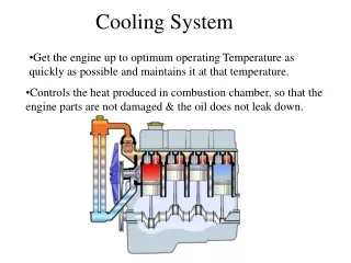
Cooling system development
This document outlines the development roadmap for the cooling system utilized in experimental areas, focusing on the integration of various components such as evaporators, transfer lines, and cooling plants. Key aspects include junction box design, control hardware implementation, flow and pressure analysis, and redundancy strategies for operational reliability. Through iterative design and testing, challenges in heat exchange, micro-channel behavior, and ambient heating are addressed. The timeline spans from 2014 to 2019, detailing milestones from requirement documentation to system installation and commissioning.

Cooling system development
E N D
Presentation Transcript
Cooling system development Bart Verlaat 7 July 2014
Hardware locations UXB (Experimental area) Concentric Transfer line with chicane in shielding wall • Junction box (Near detector) • Connection to evaporator • Dummy load for tests • In and outlet sensing of evaporator fluid state • Cooling plant (CO2+chiller) • All active elements • (Pumps, Accumulators) • Control hardware UXA (Delphi area) Shielding wall Evaporator (inside detector)
Cooling system development road map • Development works from evaporator to cooling plant. • Detector evaporator development : • Output to transfer line development: • Flow condition, mass flow, temperature, pressure head, stability, cool down rate • Transfer line development: • Output to CO2 cooling plant specification: • Flow condition, pressure drop, temperature range, volume • CO2 Cooling plant development • Output to chiller specification • Sub cooling (chiller temperature) • Total heat load (detector + ambient heating + control heat) • Chiller development
Evaporator development • The evaporator development is detector specific and requires many iterations between detector group and cooling experts. • A single evaporator developed in the lab must work together with all the other evaporators • Flow distribution • Pressure drop characteristics • The above means something like understanding the behavior in graphs as shown. • Challenges • Micro channel behavior • Vertical channels • Special junction box for the VELO with safety volume
Transfer line development • The right transfer line design together with the evaporator behavior determines the plant in and out put conditions. • Important transfer line inputs to the plant development is: • Pressure drop of return line (Dynamic and static) • Heat exchange capacitance = operational temperature range • Ambient heating = chiller capacity • Volume = accumulator volume
Plant development • Go for a full industrial design and production? • How to deal with redundancy? • As a baseline, the strategy chosen for the CMS cooling plants looks appealing. (Two plants normally in use, where each plant is able to take the full load in case of problems with one plant or maintenance needs.) • Any new development needed, or can we fully rely on past experience? • Where to place the system? New location?
Possible timeline • 2014 • Q34: Requirement document by VELO and UT • 2015 • Q12: Development and definition of evaporator systems • Q23: Concept P&ID • Preliminary sizing • Control philosophy • Redundancy approach • Q3: P&ID document & functional analyses • Q3 2015 :Cooling EDR • Q4 start of design • 2016 • Q123 Detailed design of hardware • Evaporator, junction box, transfer line, cooling plants • Q3 2016: Cooling PRR • Q4 Production of transfer line and junction box • Q4 19 weeks winter shutdown (EYETS) • 2017 • Q1 Transfer line and junction box installation • Q1234 Production of the cooling hardware • 2018 • Q12 cooling system installation in UXA (on top of D3 ?) • Q234 Cooling system over junction box commissioning • Q3 start of LS2 • Q3 Removal of current VELO and UT • 2019 • Q1 Cooling system commissioning • Q2 Upgrade VELO and UT installation • Q34 Detector commissioning with cooling • Q4 end of LS2 Main questions: When can we pass the shielding wall for the transfer line? Is an installation in EYETS possible to win time in LS2? Can we foresee as possible location for the cooling plant the top of D3? This would allow to anticipate the installation to the last part of LHC Run II.