Download
1 / 19
190 likes | 295 Vues
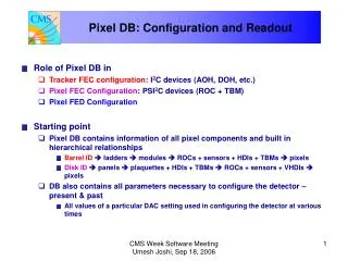
Pixel DB: Configuration and Readout. Role of Pixel DB in Tracker FEC configuration : I 2 C devices (AOH, DOH, etc.) Pixel FEC Configuration : PSI 2 C devices (ROC + TBM) Pixel FED Configuration Starting point

E N D
Pixel DB: Configuration and Readout • Role of Pixel DB in • Tracker FEC configuration: I2C devices (AOH, DOH, etc.) • Pixel FEC Configuration: PSI2C devices (ROC + TBM) • Pixel FED Configuration • Starting point • Pixel DB contains information of all pixel components and built in hierarchical relationships • Barrel ID ladders modules ROCs + sensors + HDIs + TBMs pixels • Disk ID panels plaquettes + HDIs + TBMs ROCs + sensors + VHDIs pixels • DB also contains all parameters necessary to configure the detector – present & past • All values of a particular DAC setting used in configuring the detector at various times CMS Week Software Meeting Umesh Joshi, Sep 18, 2006
Pixel DB: Configuration and Readout • Address all pixel devices using the names specified in the Pixel Naming document • The DB will contain maps of a device name to all quantities used to specify it in the detector • For example, a ROC on a forward pixel panel will be mapped to its placement on a • Plaquette • Panel • Readout sequence • Etc. CMS Week Software Meeting Umesh Joshi, Sep 18, 2006
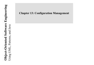
Barrel I2C Communications AOH motherboard CCU CCU CCU copper I2C CCU To modules CCU DOH CCU CCU CCU Fiber (token ring) DOH motherboard CCU TrkFEC PLL VME DOH DOH Delay25 Delay25 CAEN Controller AOH AOH AOH AOH AOH AOH AOH AOH AOH AOH AOH AOH TrkFEC Supervisor CMS Week Software Meeting Umesh Joshi, Sep 18, 2006
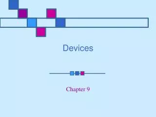
Port cards Forward I2C Communications To panels copper I2C CCU CCU CCU DOH CCU CCU Fiber (token ring) TrkFEC VME AOH AOH CAEN Controller DCU DCU DOH DOH PLL PLL Delay25 Delay25 TrkFEC Supervisor CMS Week Software Meeting Umesh Joshi, Sep 18, 2006
Pixel I2C Configuration Data to be downloaded by Tracker FEC • Barrel • 4 mFECs, each connected to a control network • ID: VME addresses • 1 CCU / sector • Identification: node number • 1 AOH & 1 DOH motherboard / CCU • 8 CCUs / control network (shell) • Forward • 4 mFECs, each connected to a control network • 1 port card / 3 blades (1 disk) • 1 CCU / octant (2 disks) 2 port cards • 4 CCUs / control network (half-cylinder) CMS Week Software Meeting Umesh Joshi, Sep 18, 2006
Forward I2C Configuration AOH: 2 modules (6 lasers) each with 4 internal registers each Base addresses: 0X10 & 0X14 DOH: 1 DOH per Port Card 4 registers Base address: 0X70 PLL: 1 PLL mounted on the Port Card (5 registers) Base address: 0X20 Delay25: 1 mounted on Port Card (6 registers) Base address: 0X30 DCU: 1 DCU mounted on the Port Card (8 registers) Base addresses: 0X50 0X60 CMS Week Software Meeting Umesh Joshi, Sep 18, 2006
Barrel I2C Configuration Base I2C Addresses (AOH motherboard) I2C controller 1 (Layers 1&2)I2C controller 3 (Layer 3) AOH-1A 0x08 AOH-5A 0x08 AOH-1B 0x0C AOH-5B 0x0C AOH-2A 0x10 AOH-6A 0x10 AOH-2B 0x14 AOH-6B 0x14 AOH-3A 0x18 AOH-3B 0x1C AOH-4A 0x20 AOH-4B 0x24 Base I2C addresses (DOH motherboard) DEL-1: 0x60 PLL-1 : 0x40 PLL-3: 0x40 DOH-1: 0x70 DOH-3 0x70 CMS Week Software Meeting Umesh Joshi, Sep 18, 2006
Initialization of I2C Devices DB Access • DB maintains relationships between all components • Specification of a particular mFEC allows identification of all connected components • Allows TrackerFecSupervisor to access all I2C download parameters by simply specifying a particular mFEC (control network) • Retrieve mFEC ID + CCU ID + I2C Controller ID + I2C register + register value CMS Week Software Meeting Umesh Joshi, Sep 18, 2006
Barrel: PSI2C Initialization AOH motherboard copper Modules (max 28) To PixFED fibers (max 36) module module module fiber (digital) (PSI2C) module module HUB Port 4 TBMS PixFEC copper DOH motherboard A B VME Port 3 ROC 12 - 15 Port 2 ROC 8 - 11 PLL CAEN Controller Port 1 ROC 4 - 7 DOH DOH Port 0 ROC 0 - 3 Delay25 Delay25 AOH AOH AOH AOH AOH AOH AOH AOH AOH PixFEC Supervisor AOH AOH AOH CMS Week Software Meeting Umesh Joshi, Sep 18, 2006
Forward: PSI2C Initialization Panel fibers (6 each) Port cards Port card To PixFED Adapter board DCU DCU copper AOH AOH DCU DCU Adapter board Panel fiber (digital) (PSI2C) AOH AOH Delay25 Delay25 DOH DOH PLL PLL Delay25 Delay25 PixFEC Panel VME HUB Port 4 TBMS CAEN Controller A B Port 3 Plaq Port 2 Plaq Port 1 Plaq PixFEC Supervisor Port 0 Plaq TBM chipset CMS Week Software Meeting Umesh Joshi, Sep 18, 2006
PSI2C Network Configuration • mFEC has two sets of optical links (four fibers each) • Barrel: Connect 2 DOH motherboards (1/ link set) • Forward: Connect 2 Port cards (1/link set) • Optical link terminates at DOHmotherboard (port card) • Signals converted to electrical and fanned out to modules (panels) • 1 hub per module (panel) • Hub address: 5 bits wide (max: 32) • 5 ports per hub • Port address: 3 bits • Port 4 always occupied by TBM (TBM A & TBM B) • Ports 0 3 for ROCs CMS Week Software Meeting Umesh Joshi, Sep 18, 2006
PSI2C Network Configuration • Barrel: 4 ROCs per port • Forward: 1 plaquette per port • ROC address: 4 bits (PSI2C) • Address starts from 0 and increases sequentially in the order in which the token is passed. • Exception: Barrel modules with dual TBM readout. • Addresses of ROCs readout by TBM B start at 8 • TBM address is fixed: 0XE0 (A) & 0XF0 (B) • Barrel: each ROC on a module has a distinct address • Forward: each ROC on a plaquette has a distinct address CMS Week Software Meeting Umesh Joshi, Sep 18, 2006
PSI2C Network Configuration • Information needed by PixelFecSupervisor to address • Barrel ROC • mFEC ID + module ID + ROC ID + pixel ID • Forward ROC • mFEC ID + panel ID + ROC ID + pixel ID • Both cases: • mFEC ID + TBM hub ID + TBM port ID + ROC ID + pixel (col, row) • DB has information on components connected to a mFEC • By simply specifying an mFEC it is possible to retrieve from DB all information necessary to configure all components connected to it CMS Week Software Meeting Umesh Joshi, Sep 18, 2006
FED Configuration • Design of the module (plaquette/panel) specifies the order in which the token is passed • This is the order in which the ROCs are readout • A FED identifies a ROC by its position in the analog output (UB) • This ID has to be mapped to the ROC (e.g. position on a module) in the DB • FED Configuration • Decoding download associated address levels (from DB) • Summary: For a ROC we know the following (in addition to others) • Placement on the wafer (history) & serial number • Placement on a module/plaquette (addressing) • Placement on a module/panel • Placement in a readout sequence CMS Week Software Meeting Umesh Joshi, Sep 18, 2006
Extras CMS Week Software Meeting Umesh Joshi, Sep 18, 2006
CMS Week Software Meeting Umesh Joshi, Sep 18, 2006
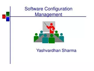
CCU25 Block Diagram Interrupts[0-3]* JTAG Master JTAG Slave Alarms CLKI(A) ST1 Trigger Decoder Clock Distribution ST2 CLKI(B) ST3 ST4 CLKO(A) Trigger Counter & other timing logic DO(A) Reset* Link Controller Node Controller DI(A) CLKO(B) DO(B) SCL SDATA I2C Master DI(B) 16 x I2C Buses Memory Bus Interface Ext Reset* Parallel interface I2C Master D[0:7] A[0:15] R/W CS[1-2]* PA[0:7] PB[0:7] PC[0:7] PD[0:7] Local Bus CMS Week Software Meeting Umesh Joshi, Sep 18, 2006
Panel Port card fiber (analog) To PixFED AOH DCU copper Adapter board Panel DOH fiber (digital) (PSI2C) PLL Delay25 copper I2C PixFEC Panel DOH VME CCU HUB Fiber (I2C) Port 4 TBM CAEN Controller TrkFEC Port 3 Plaq VME Port 2 Plaq Port 1 Plaq PixFEC Supervisor CAEN Controller Port 0 Plaq TBM chipset TrkFEC Supervisor CMS Week Software Meeting Umesh Joshi, Sep 18, 2006
Configuration Database Panel Type: HDI_3RX Plaq 0 Port 2 Plaq 1 Port 1 Plaq 2 Port 0 Panel Type : HDI_4RX Plaq 0 Port 2 Plaq 1 Port 3 Plaq 2 Port 1 Plaq 3 Port 0 Panel Type HDI_3LX Plaq 0 Port 1 Plaq 1 Port 2 Plaq 2 Port 3 Panel Type HDI_4LX Plaq 0 Port 1 Plaq 1 Port 0 Plaq 2 Port 2 Plaq 3 Port 3 • mFEC has two sets of optical links (2 Port Cards) • Optical link terminates at Port Card signals converted to electrical and fanned out to 6 adapter cards Signal ends at a hub (5 bit address) 6 hubs connected to a mFEC (link) • Each hub has 5 ports Port 4 always occupied by TBM (2 TBMs, A & B) Ports 0 3 for ROCs Forward: 1 Plaquette connected to a port Barrel: 4 ROCs per port CMS Week Software Meeting Umesh Joshi, Sep 18, 2006