Download
1 / 78
810 likes | 1.08k Vues
Lecture 6 Fading. Chapter 5 – Mobile Radio Propagation: Small-Scale Fading and Multipath. Last lecture. Large scale propagation properties of wireless systems - slowly varying properties that depend primarily on the distance between Tx and Rx. Free space path loss

E N D
Lecture 6 Fading Chapter 5 – Mobile Radio Propagation: Small-Scale Fading and Multipath
Last lecture • Large scale propagation properties of wireless systems - slowly varying properties that depend primarily on the distance between Tx and Rx. • Free space path loss • Power decay with respect to a reference point • The two-ray model • General characterization of systems using the path loss exponent. • Diffraction • Scattering • This lecture: Rapidly changing signal characteristics primarily caused by movement and multipath.
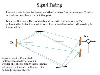
I. Fading • Fading: rapid fluctuations of received signal strength over short time intervals and/or travel distances • Caused by interference from multiple copies of Tx signal arriving @ Rx at slightly different times • Three most important effects: • Rapid changes in signal strengths over small travel distances or short time periods. • Changes in the frequency of signals. • Multiple signals arriving a different times. When added together at the antenna, signals are spread out in time. This can cause a smearing of the signal and interference between bits that are received.
Fading signals occur due to reflections from ground & surrounding buildings (clutter) as well as scattered signals from trees, people, towers, etc. • often an LOS path is not available so the first multipath signal arrival is probably the desired signal (the one which traveled the shortest distance) • allows service even when Rx is severely obstructed by surrounding clutter
Even stationaryTx/Rx wireless links can experience fading due to the motion of objects (cars, people, trees, etc.) in surrounding environment off of which come the reflections • Multipath signals have randomly distributed amplitudes, phases, & direction of arrival • vector summation of (A ∠θ) @ Rx of multipath leads to constructive/destructive interference as mobile Rx moves in space with respect to time
received signal strength can vary by Small-scale fading over distances of a few meter (about 7 cm at 1 GHz)! • This is a variation between, say, 1 mW and 10-6 mW. • If a user stops at a deeply faded point, the signal quality can be quite bad. • However, even if a user stops, others around may still be moving and can change the fading characteristics. • And if we have another antenna, say only 7 to 10 cm separated from the other antenna, that signal could be good. • This is called making use of ________ which we will study in Chapter 7.
fading occurs around received signal strength predicted from large-scale path loss models
II. Physical Factors Influencing Fading in Mobile Radio Channel (MRC) 1) Multipath Propagation • # and strength of multipath signals • time delay of signal arrival • large path length differences → large differences in delay between signals • urban area w/ many buildings distributed over large spatial scale • large # of strong multipath signals with only a few having a large time delay • suburb with nearby office park or shopping mall • moderate # of strong multipath signals with small to moderate delay times • rural → few multipath signals (LOS + ground reflection)
2) Speed of Mobile • relative motion between base station & mobile causes random frequency modulation due to Doppler shift (fd) • Different multipath components may have different frequency shifts. 3) Speed of Surrounding Objects • also influence Doppler shifts on multipath signals • dominates small-scale fading if speed of objects > mobile speed • otherwise ignored
4) Tx signal bandwidth (Bs) • The mobile radio channel (MRC) is modeled as filter w/ specific bandwidth (BW) • The relationship between the signal BW & the MRC BW will affect fading rates and distortion, and so will determine: a) if small-scale fading is significant b) if time distortion of signal leads to inter-symbol interference (ISI) • An MRC can cause distortion/ISI or small-scale fading, or both. • But typically one or the other.
Doppler Shift • motion causes frequency modulation due to Doppler shift (fd) • v : velocity (m/s) • λ : wavelength (m) • θ : angle between mobile direction and arrival direction of RF energy • + shift → mobile moving toward S • − shift → mobile moving away from S
Two Doppler shifts to consider above 1. The Doppler shift of the signal when it is received at the car. 2. The Doppler shift of the signal when it bounces off the car and is received somewhere else. • Multipath signals will have differentfd’s for constant v because of random arrival directions!!
Example 5.1, page 180 • Carrier frequency = 1850 MHz • Vehicle moving 60 mph • Compute frequency deviation in the following situations. (a) Moving directly toward the transmitter (b) Moving perpendicular to the transmitter
Note: What matters with Doppler shift is not the absolute frequency, but the shift in frequency relative to the bandwidth of a channel. • For example: A shift of 166 Hz may be significant for a channel with a 1 kHz bandwidth. • In general, low bit rate (low bandwidth) channels are affected by Doppler shift.
III. MRC Impulse Response Model • Model the MRC as a linear filter with a time varyingcharacteristics • Vector summation of random amplitudes & phases of multipath signals results in a "filter" • That is to say, the MRC takes an original signal and in the process of sending the signal produces a modified signal at the receiver.
Time variation due to mobile motion → time delay of multipath signals varies with location of Rx • Can be thought as a "location varying" filter. • As mobile moves with time, the location changes with time; hence, time-varying characteristics. • The MRC has a fundamental bandwidth limitation → model as a band pass filter
Linear filter theory y(t) = x(t)⊗ h(t)or Y ( f ) = X( f )⋅H ( f ) • How is an unknown h(t) determined? • let x(t) = δ(t)→ use a delta or impulse input • y(t) = h(t)→ impulse response function • Impulse response for standard filter theory is the same regardless of when it is measured → time invariant!
How is the impulse response of an MRC determined? • “channel sounding” → like radar • transmit short time duration pulse (not exactly an impulse, but with wide BW) and record multipath echoes @ Rx
short duration Tx pulse ≈ unit impulse • define excess delay bin as • amplitude and delay time of multipath returns change as mobile moves • Fig. 5.4, pg. 184 → MRC is time variant
model multipath returns as a sum of unit impulses • ai∠ θi= amplitude & phase of each multipath signal • N = # of multipath components • aiis relatively constant over an local area • But θ iwill change significantly because of different path lengths (direct distance plus reflected distance) at different locations.
The useful frequency span of the model : • The received power delay profile in a local area: • Assume the channel impulse response is time invariant, or WSS
Relationship between Bandwidth and Received Power • A pulsed, transmitted RF signal of the form
The average small-scale received power • The average small scale received power is simply the sum of the average powers received in each multipath component • The Rx power of a wideband signal such as p(t) does not fluctuate significantly when a receiver is moved about a local area.
CW signal (narrowband signal ) is transmitted in to the same channel
Average power for a CW signal is equivalent to the average received power for a wideband signal in a small-scale region. • The received local ensemble average power of wideband and narrowband signals are equivalent. • Tx signal BW > Channel BW Rx power varies very small • Tx signal BW < Channel BW large signal fluctuations (fading) occur • The duration of baseband signal > excess delay of channel • due to the phase shifts of the many unsolved multipath components
The Fourier Transform of hb( t,τ)gives the spectral characteristics of the channel → frequency response • MRC filter passband → “Channel BW” or Coherence BW = Bc • range of frequencies over which signals will be transmitted without significant changes in signal strength • channel acts as a filter depending on frequency • signals with narrow frequency bands are not distorted by the channel
IV. Multipath Channel Parameters • Derived from multipath power delay profiles (Eq. 5-18) • P (τk): relative power amplitudes of multipath signals (absolute measurements are not needed) • Relative to the first detectable signal arriving at the Rx at τ0 • use ensemble average of many profiles in a small localized area →typically 2 − 6 m spacing of measurements→ to obtain average small-scale response
Time Dispersion Parameters • “excess delay” : all values computed relative to the time of first signal arrival τo • mean excess delay → • RMS delay spread → where Avg( τ2) is the same computation as above as used for except that • A simple way to explain this is “the range of time within which most of the delayed signals arrive”
outdoor channel ~ on the order of microseconds • indoor channel ~ on the order of nanoseconds
maximum excess delay ( τX): the largest time where the multipath power levels are still within X dB of the maximum power level • worst case delay value • depends very much on the choice of the noise threshold
τ and στ provide a measure of propagation delay of interfering signals • Then give an indication of how time smearing might occur for the signal. • A small στ is desired. • The noise threshold is used to differentiate between received multipath components and thermal noise
Coherence BW (Bc) and Delay Spread ( ) • The Fourier Transform of multipath delay shows frequency (spectral) characteristics of the MRC • Bc: statistical measure of frequency range where MRC response is flat • MRC response is flat= passes all frequencies with ≈ equal gain & linear phase • amplitudes of different frequency components are correlated • if two sinusoids have frequency separation greater than Bc, they are affected quite differently by the channel
amplitude correlation → multipath signals have close to the same amplitude → if they are then out-of-phase they have significant destructive interference with each other (deep fades) • so a flat fading channel is both “good” and “bad” • Good: The MRC is like a bandpass filter and passes signals without major attenuation from the channel. • Bad: Deep fading can occur.
so the coherence bandwidth is “the range of frequencies over which two frequency components have a strong potential for amplitude correlation.” (quote from textbook)
estimates • 0.9 correlation → Bc ≈ 1 / 50 (signals are 90% correlated with each other) • 0.5 correlation → Bc ≈ 1 / 5 Which has a larger bandwidth and why? • specific channels require detailed analysis for a particular transmitted signal – these are just rough estimates
A channel that is not a flat fading channel is called frequency selective fading because different frequencies within a signal are attenuated differently by the MRC. • Note: The definition of flat or frequency selective fading is defined with respect to the bandwidth of the signal that is being transmitted.
Bcand στ are related quantities that characterize time-varying nature of the MRC for multipath interference from frequency & time domain perspectives