Download
1 / 54
580 likes | 809 Vues
Fundamentals of Strapdown Inertial and GPS-Aided Navigation By Professor Dominick Andrisani Purdue University, West Lafayette, IN 47907-1282 andrisan@ecn.purdue.edu 765-494-5135 Tactical Imagery Geopositioning Workshop March 12, 2002 Chantilly, VA. Purposes of this talk.

E N D
Fundamentals of Strapdown Inertial and GPS-Aided Navigation By Professor Dominick Andrisani Purdue University, West Lafayette, IN 47907-1282 andrisan@ecn.purdue.edu 765-494-5135 Tactical Imagery Geopositioning Workshop March 12, 2002 Chantilly, VA
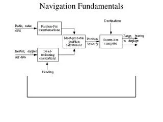
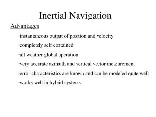
Purposes of this talk • To provide a tutorial overview of inertial navigation systems (INS). • Illustrate ideas with a 2-D navigator. • Discuss inertial sensors (simple rate gyros and linear accelerometers). • Discuss characteristic errors in the INS. • To demonstrate the need by the INS for altitude aiding. • To show how GPS aids the INS and leads to far superior navigation accuracy.
Types of Inertial Navigation Systems (INS) Inertial Platform based INS Strapdown INS <<(emphasized here) Aided Navigators of either type • Altitude-aided • Altitude and X-aided • Heading-aided • GPS aided
Inertial Platform Ref 4.
Strapdown INS Ref 4.
Properties of Platforms Advantages Simpler gyros (platform rotates at small rates, lower dynamic range). High accuracy (North and East accelerometers do not see a component of gravity). Self alignment by gyro compassing. Sensor calibration by platform rotations. Disadvantages Complexity and cost. Gimbal magnetics (torquers must not leak magnetic flux). Reliability (bearings and slip rings tend to wear).
Properties of Strapdown Systems Advantages Simple structure, low cost. More rugged and lighter. Reliability (no gimbal magnetics, no slip rings, no bearings, electronics more reliable then machinery). Disadvantages More difficult to align. More difficult to calibrate. Motion induced errors which can only be partly compensated for. Accelerometer errors (each accelerometer may feel 1 g from gravity). Requires a computer that can perform coordinate rotations in <.01 sec).
Simple Example: Two Dimensional Motion Xb, Yb, and Zb are body fixed Yb=YNED . Xb Pitch angle q XNED XNED is northerly YNED is easterly ZNED is down North Pole ZNED Zb South Pole
Equations of Motion of the Aircraft • dQ/dt=vx/(Ro+h) + wy • dvx/dt =vxvy/(Ro+h) + fx • dvz/dt =-vz2/(Ro+h) + fz + g(h) • dx/dt =vx • dh/dt =-vz • where • fx=fxbcos(Q)+fzbsin(Q) • fz=-fxbsin(Q) + fzbcos(Q) • is pitch angle vx is velocity in northerly direction vz is velocity in down direction x is northerly position h is altitude (positive up)
Inertial Sensors Rate gyros measure the components of inertial angular rate of the aircraft in the sensitive direction of the instrument. Linear accelerometers are used to measure the components of aircraft linear acceleration minus the components of gravity in its sensitive direction. Newton’s Law for the aircraft is F=ma=Faero+Fthrust+mg Accelerometer measures a-g=(Faero+Fthrust)/m=specific force In this simple two-dimensional example, two linear accelerometers and one rate gyro are used.
A Single Axis Angular Rate Gyro This device measures inertial angular rate about its sensitive direction. Three of these arranged orthogonally measure the components of the angular velocity vector. Ref 3.
A Simple “Open Loop” Accelerometer This device measures specific force= a-g=(Faero+Fthrust)/m. They cannot distinguish between acceleration and gravity. g Ref 3.
Aircraft Simulation Coriolis acceleration Coriolis acceleration Transport rate
INS Free Integrator • The free integrator will create the following types of errors. • For initial condition errors on x, the resulting x-position error will neither decay or grow. • For initial condition errors on Vx, the resulting x-position errors will grow linearly with time.
INS Simulation (Unstable Altitude Loop) Unstable Altitude Loop
INS Unstable Altitude Loop The unstable altitude loop results because errors in altitude means that there will be errors in the determination of the acceleration of gravity. This in turn will propagate into an error in vertical acceleration which will be in the direction to drive the altitude error further from the correct value. This is an unstable mechanism since altitude error leads to greater altitude error.
INS Simulation (Schuler Pendulum) Schuler Pendulum Loop
Schuler Pendulum Loop The Schuler pendulum loop creates dynamic errors that oscillate with an 84 minute period. The Schuler pendulum loop, while creating persistent oscillations, does limit the growth of errors in velocity (Vx).
The Schuler Pendulum • Imagine we have a pendulum to provide a vertical reference. • As we accelerate horizontally, the pendulum tilts, giving a false vertical indication. • Schuler showed that this would not occur with a pendulum having a period of 84 minutes (a ball on a string with length equal to the radius of the Earth has this period). • Correcting an inertial system so that it does not tilt when accelerated is known as Schuler tuning.
Error Analysis Via Linearization Nonlinear navigator equations of motion dX/dt=f(X,U) Error model e=XINS-Xsimulation u=UINS-Usimulation Linear error equations of motion de/dt=Ae+Bu where A=df/dX evaluated at the a reference state X and input U) B=df/dU evaluated at the a reference state X and input U)
Error Analysis Via Linearization, continued Linear error equations of motion de/dt=Ae+Bu with initial condition e(0) System matrix A will have 5 poles (eigenvalues), two complex poles for the Schuler Pendulum, two real poles for the altitude modes (one unstable, one stable, equal magnitude), and one pole at zero (X-pole). The error system provides a useful way to study INS error propagation using linear methods and as the basis for designing Kalman filters to implement the various aiding techniques (e.g. altitude aiding).
Nonlinear Simulation of Aircraft and INS Given three inputs, we can find all outputs including errors.
Error Analysis Using Nonlinear Simulation Examine navigation errors when the IC on X is in error.
Error Due to X Initial Condition Errors remain constant.
Simulation of Aircraft and INS Examine navigation errors when the IC on H is in error.
Errors Due to H initial Condition Errors are dominated by unstable altitude mode.
Simulation of Aircraft and INS Examine navigation errors when IC on Vx is in error.
Errors Due to Vx Initial Condition In the flat earth navigator the X-error would go to infinity. The Schuler pendulum mode limits the X-error. Note both Schuler oscillation and unstable altitude mode.
INS Aiding Altitude Aiding Velocity and position errors in the vertical channel are not bounded and can quickly become quite large. Barometric altitude provides a measure of height above sea level, typically to an accuracy of 0.1%. Most airborne INS operate with barometric aiding in order to bound the growth of vertical channel errors. Many other types of aiding are typically used
Altitude-aided INS Includes a steady state (constant gain) Kalman filter with gains on (Hmeasured-Hestimated).
Altitude and X-aided INS Includes a steady state (constant gain) Kalman filter with gains on (Hmeasured-Hestimated) and (Hmeasured-Hestimated).
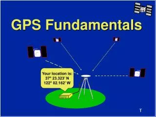
GPS Aiding of INS GPS can provide aiding to an INS by providing an independent measurement of x, y, and z (altitude). Furthermore, certain GPS implementation can provide velocity aiding by providing independent measurements of Vx, Vy and Vz. A Kalman filter is often used to help blend the GPS measurements with the INS outputs in an optimal way.
Integrated INS/GPS Block Diagram Velocity Position Orientation accelerations angular rates
Measurements from the GPS Receiver Model Pseudorange Pseudorange Rate : Satellite Position : Platform Position : Pseudorange equvalent Clock Bias (Random Walk) : Pseudorange rate equivalent Clock Drift (Random Walk) : Normally Distributed Random Numbers
Benefits of Integrated INS/GPS Systems • INS gives accurate estimates of aircraft orientation. • GPS provides accurate estimates of aircraft position. • INS solutions are generally computed 100 times per second. • GPS solutions are computed once per second. • GPS in subject to jamming, INS is not. • Combining GPS and INS provides accurate and robust determination of both translational and rotational motion of the aircraft. • Both translational and rotational motion are required to locate targets on the ground from the aircraft.
Conclusions Unaided INS have troublesome errors that grow with time or oscillate with an 84 minute period. Various aiding schemes are often implemented to stabilize the INS errors. GPS aiding of INS is an effective means to stabilize INS position and velocity errors. Integrated INS and GPS systems are useful for determining both the position and orientation of an aircraft. Such systems are therefore helpful in locating of targets on the ground.
Additional Purdue Resources Presented at the The Motion Imagery Geolocation Workshop, SAIC Signal Hill Complex, 10/31/01 1. Dominick Andrisani, Simultaneous Estimation of Aircraft and Target Position With a Control Point 2. Ade Mulyana, Takayuki Hoshizaki, Simulation of Tightly Coupled INS/GPS Navigator 3. James Bethel, Error Propagation in Photogrammetric Geopositioning 4. Aaron Braun, Estimation Models and Precision of Target Determination Presented at the The Motion Imagery Geopositioning Review and Workshop, Purdue University, 24/25 July, 2001 • 1. Dominick Andrisani, Simultaneous Estimation of Aircraft and Target Position • 2. Jim Bethel, Motion Imagery Modeling Study Overview • 3. Jim Bethel, Data Hiding in Imagery • 4. Aaron Braun, Estimation and Target Accuracy • 5. Takayuki Hoshizaki and Dominick Andrisani, Aircraft Simulation Study Including Inertial • Navigation System (INS) Model with Errors • 6. Ade Mulyana, Platform Position Accuracy from GPS
References • 1. B.H. Hafskjold, B. Jalving, P.E. Hagen, K. Grade, Integrated Camera-Based Navigation, Journal of Navigation, Volume 53, No. 2, pp. 237-245. • 2. Daniel J. Biezad, Integrated Navigation and Guidance Systems, AIAA Education Series, 1999. • 3. D.H. Titterton and J.L. Weston, Strapdown Inertial Navigation Technology, Peter Peregrinus, Ltd., 1997. • 4. A. Lawrence, Modern Inertial Technology, Springer, 1998. • 5. B. Stietler and H. Winter, Gyroscopic Instruments and Their Application to Flight Testing, AGARDograph No. 160, Vol. 15,1982. • A.K. Brown, High Accuracy Targeting Using a GPS-Aided Inertial Measurement Unit, ION 54th Annual Meeting, June 1998, Denver, CO.