Download
1 / 22
240 likes | 352 Vues
800 MeV Injection into Booster in the PIP-II Era. David Johnson AD/PIP-II Department October 14, 2014. Beams-doc 4683. Parameters. Existing Booster injection (400 MeV) 5E12 @ 7.5 Hz (soon to be upgraded to 15 Hz for PIP) 2.4 kW beam power at injection

E N D
800 MeV Injection into Booster in the PIP-II Era David Johnson AD/PIP-II Department October 14, 2014 Beams-doc 4683
Parameters • Existing Booster injection (400 MeV) • 5E12 @ 7.5 Hz (soon to be upgraded to 15 Hz for PIP) • 2.4 kW beam power at injection • Foil thickness 380 mg/cm2 should give 99.9% stripping efficiency (2W loss) • 20 mr/hr @ 1 ft due to neutrals (downstream loss point on 2nd GM) • Assume ½% lost by other means (10W loss) • 100 mr/hr @ 1 ft due to H- missing foil (upstream loss point on 2nd GM) • Injection time < 35 us (for 16 turns) • PIP-II Operational Parameters (800 MeV) • 6.633E12 @ 20 Hz for ~ 17 kW injected beam power (x7increase) • Linac 95% normalized emittance 1.5 p-mm-mr (H&V) • Booster final 95% normalized emittance 16 p-mm-mr (H&V) • Injection time ~560 us Injection turns ~315 • PIP-II Beam loss at injection assumptions • H- conversion efficiency 99.9% • Foil thickness increase from 380 to 545 • Implies 17 W to absorber • H- missing foil 2% • Implies 340 W to absorber
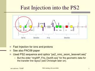
Existing Booster – Straight Section No injection absorber 6m (to laminations) Waste beam lost in 2nd gradient magnet downstream PIP-II power increases X7 -> ~17 kW Figure from Jim Lackey ‘07 PAC paper ~0.23m 70 mr Installed 2006
PHYSICAL LAYOUTOF INJECTION GIRDER (223.64”) Flange-flange 5.6804m 0.167 m 2.8891 m 0.1524 m Bypass 3.2087 m H- valve valve Vacuum Box Foil Changer ORBUMPs Scanning wire
Current Geometry Real Estate • Existing Equipment fit within 223.64” • BPM assembly 12.46” • 3 Orbump magnets (28.808”) 86.424” • Vacuum box to merge inj. Beam 48.538” • Vacuum bypass (2) 20.86” • Vacuum valves (2) 5.52” • Foil changer 12.25” • Crawling wire (diagnostics) ~ 6” • Correction package ~19.43” (17” steel 5” aperture) • Total real estate used 211.482” • Drift space/connections/etc. 12.155”
Ideal Design features • Separate chicane and painting dipoles • Chicane operate on both circ. and injected beam • Painting dipoles operate only on circulating beam • Separate foil from circulating beam • Well shielded absorber for injected waste beam not to interfere with circulating beam • Vacuum bypass for foil changer • Injection diagnostics (bpm & profile monitor for waste beam)
Options for New Design • Chicane Geometry -> Vertical • Relative Horizontal & Vertical beam size at foil • Limited vertical aperture of surrounding gradient magnets • Chicane dipoles double duty as vertical painting magnets • Horizontal painting magnets outside straight • Three or four bump design • Make things fit with existing straight, or • EXPAND existing straight by shortening defocusing gradient magnets
Initial Conceptual Design • Length of Booster straight section remains un changed. • Three bump design (vertical chicane) • Single magnet at each end • Two magnets in the middle • Use chicane dipoles for vertical painting • Requires new magnet • Requires new power supply • ~500 us vs 30 us injection time • Flattop waveform changes during injection time for painting (C.O.-> 45mm to 30 mm • Use horizontal dipoles outside straight for horizontal painting (not included yet in model) • Injected H- position at foil (~45mm V & ~5mm H) • H- injection line comes into ORBUMP #2 at an angle of 114 mr • Separation between ORBUMP 1 & 2 and 3&4 at 1.01 meter
6” aperture 5” aperture
Injection Beam Line Lattice Red- circulating lattice Green – injection lattice • Circulating beam closed orbit motion • start centered on green ellipse • move to zero dx=7.5 mm dy=15 mm • Lattice function mismatch to minimize • foil hits from circulating beam • betax 4.88 ring vs 2.1 beam line • betay 18.52 ring vs 8.0 beam line • alfax&y = 0 for upright ellipse FOIL C-magnet • Beam line must match (or miss-match) all 8 lattice parameters
What is included # • GM and 1st ORB 0.2409* m (eff. 0.08 m) • ORB #1 0.6917 m • Between 1st & 2nd ORB 1.01 m • ORB #2a 0.6917 m • Between 2nd & 3rd ORB 0.0 m • ORB #2b 0.6917 m • Between 3rd PM and Foil 0.1012 m • Foil Changer 0.3048 m • Between foil and 4th ORB 0.605 m • ORB #3 0.6917 m • Between 4th ORB and Absorber 0.30 m • Absorber 0.5 m • Between absorber and GM 0.171* m (eff. 0.01 m) Available space to install equipment * About 0.16 of this distance is for gradient magnet flange . #What’s not: ion pumps, vacuum valves, vacuum bypass, corrector package, diagnostics
Active Elements • Vertical Chicane (c.f. ORBUMP) • Injection magnet from beam line (c.f. c-magnet) • Horizontal painting magnets in ring (NOT specified or included yet) • Foil changer • Absorber • Diagnostics
Vertical Chicane Current Opt 1 Opt 2 • Angle * [mr] 22 40 35.7 • Offset @ foil [mm] 45 45 40 • Offset @ center magnet [mm] 68.6 61 • Integrated field [ kG-m] 1.676 1.952 1.743 • Field [kG] 3.0 3.496 3.121 • Effective length 0.5585 m (same as existing ORBUMP) • Flange-flange length 0.6917 (reduction of 40 mm) • Gap 65.1 mm (un-changed) • Aperture 100mm for first & last 190-200 for center magnet *Assume ~ 1 meter separation between chicane dipoles . At 40 mr, H0 hits top of absorber about 0.15m downstream of face @ 2.3o At 35.7 mr, H0 hit top of absorber about 0.25m downstream of face @ 2o
Existing ORBUMP • Design: Single turn window frame magnet with most current concentrated in 1 mm area close to magnet aperture. • Used best CMD10 ferrite with Bs=0.46 T. • How to get higher field: • increase field by increasing current and/or reduce the gap • ferrite saturation • Field homogeneity in the gap • Increase effective length • Increases stored energy, hence inductance • No room in straight section • Use a material like Finemet with Bs= 1T • Thin laminations - Indutctive (transverse impedance issues?) • Very expensive QD CF Aperture: H 65.1 mm V 135.1 mm Half-height 175.5 mm flange to eff. length flange to eff. length 0.1217m 0.0515m 0.5585m 0.02743 m 0.09755m 0.60673m f-f 0.7317m
Injection C-magnet • For the 45 mm foil offset • Entrance into c-magnet 278 mm & 0 mr • Exit of c-magnet v210 mm & -114 mr • Entrance into the upstream flange of the 2nd ORBUMP at 152 mm & -114 mr • Vertical sigma of injected beam ~1.15 mm • Beam pipe/gap > 10s -> estimate 1 inch • Could have 8 turn magnet with 1200A • Can be DC. • Length 1.2 m (not in Booster straight) • Angle 114 mr -> 5.564 kG-m -> 4.64 kG • Lab frame lifetime 20 us loss rate ~2e-04/m • Similar in design to ICA
Absorber • Should handle 375 watts routine running • 0.2% Neutrals & 2% H-minus (optimistic) • Design for factor 2 larger (?) • Loss protection for X % linac pulse full intensity • Should provide at least 3 nuclear interaction lengths. 10 cm in W and 17 cm Fe) • 30cm W and 51 cm Fe • Absorber material Tungsten alloy • Need to define shielding around absorber (how much, what type) What is out scattering cone? H-minus (4 deg) 1.2 mm (2 deg) ~35 mm H0 3.5 mm 25 mm 50 mm
Issues • We need to make space for • Ion pumps • Vacuum valves • Vacuum bypass • Correction element package (5” aperture) • Don’t currently see where this can go • Diagnostics (for injection, circ. Beam, waste beam) • Aperture in center PM • increase 40% over existing ORBUMP • Absorber geometry
Alternative • It’s clear the existing straight is marginal at best • Look at a design which increases straight section length • Means making 2 new Booster “D” Gradient magnets • Magnet construction • Power supply tuning of lumped inductance • Added expense • Look at a 4 bump design • Smaller chicane dipole apertures • Better impact parameters for absorber • Room for correction element package • Use same foil offset as 3 bump (45 mm) • Includes existing vacuum valve& bypass • Includes room for correction element package • Diagnostics could be included in face of absorber • Still tight (have not included or specified horizontal painting magnets • May need to investigate paint (V) steer from beam line (H)
Booster Gradient Magnet Proposal Mike May • Simpler construction • Coils outside vacuum • Similar construction to • Lambertsons • Want to match bend angle (BL) vs current to existing magnets over full ramp • Gradient should be ~98% nominal to compensate mismatch • Change in effective length vs excitation should match existing magnets • Length reduces by ~30% Increases straight section by ~0.87 m. • Number turns increase from 28 to 40
Current Plans • Investigate options for vertical chicane • Magnet design (what are the limitations) • Power supply design (20Hz resonant vs ramped) • Field requirements for 3 bump (Opt. 2) & 4 bump similar i.e ~3.2 kG • Determine what’s required to fit the correction element package into the current 3 bump design or the impact of breaking symmetry • Determine where the horizontal painting magnets can be installed and their magnet parameters • Start simulations for absorber (Igor R will return first part of November) to determine a preliminary design (starting with 3 bump configuration) • Start looking at potential painting algorithms (compatible with chicane magnet & p.s. design) • Specify Booster gradient magnet properties, look at preliminary magnetic design, and the impact on the power supply.