PIP II Booster
PIP II Booster. William Pellico PIP-II Machine Advisory Committee 15 - 17 March 2016. O utline. Present Booster operations Booster numbers t oday PIP numbers and goals relative to PIP II PIP II Booster PIP II Booster parameters Systems impacted by PIP II Injection/ c apture RF

PIP II Booster
E N D
Presentation Transcript
PIP II Booster William Pellico PIP-II Machine Advisory Committee 15 - 17 March 2016
Outline • Present Booster operations • Booster numbers today • PIP numbers and goals relative to PIP II • PIP II Booster • PIP II Booster parameters • Systems impacted by PIP II • Injection/capture • RF • 20 Hz operations • Beam dynamics/loss control • Misc. – long term viability, reliability and loses William Pellico | P2MAC_2016
Planned Booster Peak Flux and Users ~PIP end NOW Preparing for PIP II Flux Ramp Up Summer shutdown William Pellico | P2MAC_2016
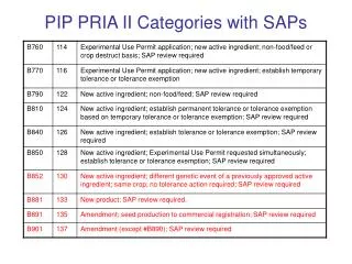
PIP Booster parameter table William Pellico | P2MAC_2016
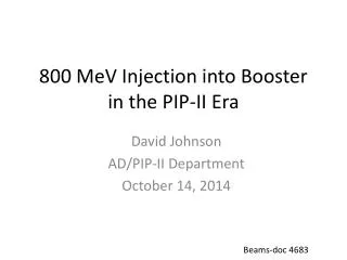
PIP II Booster PIP II will generate > 50% higher flux than the planned PIP operations PIP flux FY17: 2.3e17 pph PIP-II flux: 3.5e17pph(15Hz) PIP-II flux: 4.6E17pph (20Hz) William Pellico | P2MAC_2016
PIP II injection point into Booster - reminder Present injection point at L1 New injection point at L11 William Pellico | P2MAC_2016
PIP II required R&D: Areas of progress under PIP • New injection point at L11 • New injection girder • Space charge mitigation: painting • New stripping foil system • H0 , H- absorber • RF Cavity investigation/design/construction • RF capture • capture scheme: Direct injection into buckets preferred (adiabatic: 2nd choice) • 2nd harmonic cavities (considered but probably unnecessary) • Transition crossing • RF focusing method • Beam/RF simulations (V. Lebedev – for PIP II) • RF focus free method (flattening of RF amplitude) • 2nd or 3rd harmonic cavities. (can also be used in RF focusing method) • gt jump system (not likely) • requires resurrection/rebuild of old system William Pellico | P2MAC_2016
R&D Overview (cont’d) • Damper upgrades and collimation system • Longitudinal quadrupole damping when going through transition • Longitudinal coupled bunch mode damping at high field • Transverse dampers for coupled bunch modes • Evaluation of present collimation system w.r.t. expected PIP II • Beam quality at extraction • Emittances determined by Recycler admittances • 20 Hz operations and components • GMPS • Pulsed systems • Controls William Pellico | P2MAC_2016
Tunable Booster cavities – two options being studied H h h H William Pellico | P2MAC_2016
Perpendicularbiased cavities (part of PIP – PIP II possibilities) Simulations of use at injection/transition for PIP I is underway. Standard Booster PA The goal is 100 kV gap for a cavity that is about half the length of present Booster/MI cavity. Garnet Rings Vacuum Windows • Ferrites with relatively low saturation magnetization • (Mn-Zn) • Smaller values of m • (smaller losses, larger Q) • Small space required but high gradient • Cooling is difficult • Vacuum windows location 3.25 aperture Area of localized heating G. Romanov, CY Tan, Ding Sun, Kevin Duel, Robyn Madrak, Mohamed Awida, Iouri Terechkine William Pellico | P2MAC_2016
Second Harmonic (perpendicular) continued Hminhas increased from ~33 Oe to ~50 Oe Material of shim – Al800 Thickness – 3.5 mm Inner radius – 115 mm Outer radius – 148 mm Fillet radii – 2.5 mm Ferrite disks: Upper 16 mm Others 21 mm Total length 100 mm William Pellico | P2MAC_2016
Perpendicular Harmonic Continued Status & Plans: Building PA test cavity – verify range/power of PA Ordering Garnet material to make two rings discussing assembly process with vendor Discussing with vendor – window options Finalize solenoid design Plan is to start to build cavity this FY Cavity to test ferrite Anode and cathode resonator (PA testing) William Pellico | P2MAC_2016
Possible use of perpendicular design for fundamental use 1000 mm 82.5 mm 346 mm Design features:- –High R/Q (geometry is optimized to have R/Q>=50 over the frequency range) –Relatively large bore (3.25”) –Short length (1 m long) –Using available Ferrite rings, similar to the ones used for the 2ndharmonic cavity (each is 1” thick, 13.6” diameter) –Dielectric loading is used at the ferrite interface to concentrate the fields at the coupling region in order to achieve the desired sweep range (sweep range 36.6 MHz to 53.7 MHz; more than needed) –Facilitate cooling of the ferrites by thermal paths through copper (cooling channels) and dielectric washers –60 kV gap voltage –Simple Vacuum window William Pellico | P2MAC_2016
Standard Booster cavity modeling/mods – nearly complete Electric Field for 60 kV Electric Field for 55kV • Ferrites with high saturation magnetization (Ni-Zn) • Larger values of m (larger losses, lower Q) • Known technology and operations • Relatively limited by the heating in the ferrites • Large size • Low gradient • Thermal/mods testing about done then • decide on cavity • manufacturing (soon)! 3.3 MV/m 3.6 MV/m 1.85 MV/m 1.7 MV/m William Pellico | P2MAC_2016
Injection / Capture Studies • Effort to optimize the process for multi-turn injection • Long duration – depending upon # of turns – ~40 us • Will work towards 60 us load times for studies • Foil crossing – losses – tails/emittances • Longitudinal control • Capture losses – make the process more adiabatic • Optimize capture to 15 Hz ramp of the Booster gradient magnets • The PIP II injection process will be much longer but the similarities and questions can be clarified. William Pellico | P2MAC_2016
Schematic of the Early Injectionwith a pseudo front-porch Impose Beam Capture in Stationary rf Buckets (=0) StartEnd Simulations have been conducted under varieties of beam conditions from injection to extraction. Begin Inj. Change in Es<0.24MeV Beam Acceleration using 37-52 MHz RF system 40s injection 175s capture for >260s (no debunching) 1/15Hz 0.0666 s Energy Acceptance > 4MeV Beam E 1.3MeV fsy = 8kHz-27kHz @ Vrf=0.035-0.4MV William Pellico | P2MAC_2016
EIS Beam Data and some Analysis (Injection) 15BT Beam; 4.9E12ppb Testing up to 5.5E12 ppb underway – will go as high as 6.5E12 for tests! Summary: Reduction in required RF voltage and lower longitudinal emittances. Still working on improving beam capture/losses. 170µs 19.2 ns B:VAPLON B:VXTPPP LE = ~0.05eVs William Pellico | P2MAC_2016
Stripping foil studies • Investigation of various density/composite foils • Losses • Lifetime • Efficiency • Foils tested include Diamond/Carbon, some double borated, and from three different vendors. • 369 ug/cm2 • 411 ug/cm2 • 420 ug/cm2 • 339 ug/cm2 • 500 ug/cm2 William Pellico | P2MAC_2016
Foil studies continued Summary of results: • Lifetime at 15 Hz seems to be reduced for some types • Lower density foils seem to reduce losses at tight transverse apertures • Likely due to foil scattering creating tails • Lower stripping efficiencies • Higher H- loss • Higher neutral loss • Thinking about solution(s) to shielding the above losses William Pellico | P2MAC_2016
Foil study results Losses reduced at transverse restricted areas for lower density foils….will go to lower density to map out parameter space Beam loss monitor at H- location - Higher H- loss as foil deteriorates William Pellico | P2MAC_2016
Injection Girder – Foil (PIP II numbers) For a std. foil thickness 380 ug/cm2(1.15 mm) 400 MeV -> 99.9% efficiency to protons 800 MeV -> 99.1% efficiency to protons To match 400 MeV efficiency at 800 MeV foil thickness needs to increase to ~ 545 ug/cm2 present foil holder present foil At 800 MeV with 7E12 injected at 15 Hz Injection power increases to ~ 13 kW For a 0.1% loss -> 13 Watts on downstream gradient magnet Need to provide injection absorber The space is very tight making an effective design difficult! William Pellico | P2MAC_2016
Booster Extraction Resonant Charging System Temperatures Enhanced Cooling Chassis modification For cooler running at 20Hz. 20Hz Running 15Hz 20Hz Internal RCC chassis Resistor Temp PS HV on William Pellico | P2MAC_2016
20 Hz testing of pulsed systems • Testing and modifications of two pulsed systems • Kickers • ORBMP (3 element pulsed injection bump) • Both systems experienced high temps in the PS systems when run at 15 Hz • Solutions were developed that improved both systems • Kickers PS improvements were demonstrated to allow operations at 20 Hz • ORBMP could only be tested at 15 Hz William Pellico | P2MAC_2016
Kicker Power Supply Upgrades Larger Fan Enhanced Cooling Chassis modification For cooler running at 20Hz. Resistor Stand-offs William Pellico | P2MAC_2016
Beam Physics for Booster - examples • PIP goal of 2.3E17 pph has been driving our studies but PIP II benefits from the effort. • Exploring the limitations and finding the optimal operating point • Optics corrections(CY Tan, K. Seiya) • Lots of new software • A greatly improved lattice • Mapping out higher order terms in the Booster gradient magnets • Orbit and Tune control (A. Waller, K. Seiya) • Software • Tune optimization • Dampers (N. Eddy, B. Pellico….) • Limitations • Growth rates • Software • Collimators (V. Kapin, R. Tesarek, T Sullivan) • New primaries collimators – better suited for 400 MeV • Improved analysis – use of MARS and MADX • New diagnostics – fast William Pellico | P2MAC_2016
Beam physics Exploring emittance growth verses intensity Emittance growth vs intensity 5.25E12 ppp Longitudinal growth vs intensity Higher intensity difficult – since not part of normal operations it does not get tuned on. Lots of parameters need to be adjusted – takes time. William Pellico | P2MAC_2016
Increasing Booster intensity – operating point adjustments What will it take to increase beam by 50% Tune scans William Pellico | P2MAC_2016
Conclusion While we wait for a funding to directly address items required for Booster PIP II operations, work is progressing under PIP and operations. Significant progress has been made in higher flux operations that directly impact PIP II plans and will help clarify additional work/studies as we transition from PIP to PIP II. • The transition will include items in the PIP II list above as well as the continuation of Booster beam physics work under PIP. Glass half full: With present loss points while operating at 2E17 pph and peak intensities of ~ 5E12 has given us confidence in higher rate/intensity operations. We will continue to identify issues and test solutions at as high intensity as operational limits allow. William Pellico | P2MAC_2016
Xtra slides • Slides from last year William Pellico | P2MAC_2016
Vertical Injection Concept Using a three-bump chicane within the unmodified length of the long straight section William Pellico | P2MAC_2016
Injection painting* for space charge mitigation Blue: injected beam(1.8 mm-mr 95% normalized emittance) Red:phase space after painting (16 mm-mr 95% normalized emittance) Yellow square is the injection foil, Red ellipse is the injected linac beam stays at a fixed position on the foil Black line indicates motion of the circulating closed orbit by H&V painting magnets in ring painting in H (~5.3 mm) & V (~9.5 mm), then vertically removed from foil. *Results of a preliminary simulation - RDR William Pellico | P2MAC_2016
New injection girder • Beam can enter either horizontally or vertically • A new 3 bump system that can take 800 MeV beam (2x stronger) • Beam painting to mitigate space charge effects because of longer injection time (0.6 ms) • Carbon foil for stripping (presently 15 turns vs 315 turns for PIPII) • Lifetime effects • New beam absorber for H0 and H- • Build inside a gradient magnet • Design new stronger and shorter gradient magnets to make space for an absorber (preferred) William Pellico | P2MAC_2016
Capture (adiabatic at 800 MeV) 0.6 ms injection time 0.4 ms adiabatic ramp to full voltage (1 MV) William Pellico | P2MAC_2016
Capture (bucket to bucket injection) Chopping 180 deg Chopping 120 deg 0.6 ms injection time Chopping is required to get the correct bunch pattern into the bucket Linac 2 mA beam current for 0.6 ms provides 7.5e12 particles May need flattened front porch for injection Using Linac energy control vs. Booster ramp control needs to be studied William Pellico | P2MAC_2016
Booster RF – present RF cavity and options being discussed Issues Present cavities will work over frequency range but reliability is a concern Modeling cavity properties Thermal issues Voltage breakdown Mechanical construction Rebuilt to operate at 15 Hz much of cavity remains original have become increasing activated have apertures that are similar to magnet – leaving no overhead for errors New Cavity Discussion Two options: To be designed for present & PIP II Booster parameters Frequency sweep Beam power Transition and bunch rotation Design to meet the higher flux PIP II and future stages Wait till FNAL HEP/accelerator plan develops Design to be compatible with a new RCS (after PIP II) William Pellico | P2MAC_2016
Transition Crossing Transition crossing at 4.2 GeV More RF for focusing during transition ~25% more RF implies 3 – 4 more RF cavities using present design (22 – 23 cavities) • Example shown here is the compensation of the effect of space charge that is defocusing before transition & focusing after transition • Increase RF voltage before transition • Increase RF voltage again to damp out quadrupole oscillation • Using quadrupole damper effectively also requires RF overhead William Pellico | P2MAC_2016
20 Hz operations • Booster magnet system • Booster is a 15 Hz resonance synchrotron • Pulsed devices • Injection bump system (above) • Extraction systems • Kickers • Septas • Correctors • Controls • Lab built around 15 Hz clock system William Pellico | P2MAC_2016
Booster Magnets - 20 Hz • We have looked at Booster 20 Hz operations several times….most recently by AD/EE support (George Krafczyk) ‘Measurements were performed on both a Booster gradient magnet and a Booster choke with the intent to compare the 15 Hz losses with the 20 Hz losses for a proposed Booster upgrade.’ • This analysis suggests that running the booster at 20 Hz with a current equal to the present 15 Hz Booster will require about 3.9% more power. Capacitor voltage will increase by about 32% and the resonant capacitor at each “Girder” must decrease from ~8.33 mF to ~4.69 mF. This also carries the implication that the RMS current per µF will also increase as well. William Pellico | P2MAC_2016