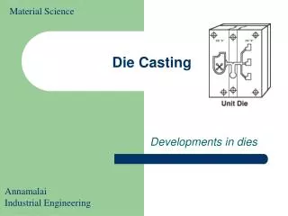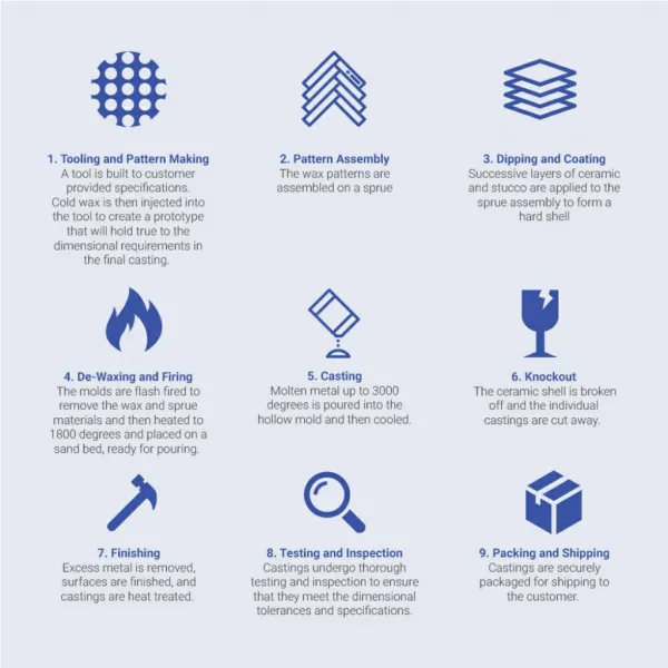
Die Casting Basics
Die Casting Basics. Die is closed. Metal is drawn in to tool (plunger). Tool injects metal into cavity. Cavity continues to fill. (fractions of a second). Metal solidifies under pressure. Die is opened. Casting removed. Machine recovers to initial orientation (cycle starts over).


Die Casting Basics
E N D
Presentation Transcript
Die Casting Basics Die is closed. Metal is drawn in to tool (plunger). Tool injects metal into cavity. Cavity continues to fill. (fractions of a second) Metal solidifies under pressure. Die is opened. Casting removed. Machine recovers to initial orientation (cycle starts over)
Stage III:Temperature Monitoring Overview • Nozzle temperature • Nozzle freezing • Die temperature • Thermal expansions • Holding pot temperature • Temperature gradients • Excess superheat
Results:Injection Pressure • Monitor weight as a function of pressure • Decreasing Pressure: • Reduces flashing • Decreases machine errors • Weight variation for each setting < 1% Pressure Dependency Analysis *Tolerance (41.24 – 43.80g)
Molten metal leaking through the gap is called ‘flashing’.
Upper Mold Atmospheric Pressure Pressurized Molten Metal Lower Mold Mold gap
Upper Mold Atmospheric Pressure Pressurized Molten Metal Lower Mold Mold gap L(t1) L(t2) L(t3) L(t4)
The approximation that the liquid:air interface velocity is equal to the average velocity of the steady stae profile was introduced by E. W. Washburn, Physical Review, vol. 17, pp. 213-283, 1921.
Further discussion of the planar interface approximation. Flow profile is disturbed at the fluid air interface Fluid Air Average velocity must be equal for incompressible fluid
γlv γsv θ γsl Complications regarding the shape of the moving solid vapor interface. Meniscus Formation Represent the surface tensions of a multi-phase junction as vectors drawn parallel to the respective surfaces The surface energies for the for the solid/liquid, the solid/vapor and the liquid/vapor interfaces are γsl, γsv, γlv The contact angle θ is a measure of the magnitude of the solid liquid interface energy compared to the solid vapor and liquid vapor energies.
γlv γsv θ γsl Youngs’ Equation Represent the surface tensions of a multi-phase junction as vectors drawn parallel to the respective surfaces The surface energies for the for the solid/liquid, the solid/vapor and the liquid/vapor interfaces are γsl, γsv, γlv. The vectors representing these surface energies must balance at the three phase triple junction. This equation representing this balance is known as ‘Youngs’ equation”
γlv γsv θ γsl γlv θ γsv γsl Large γsl, non-wetting θ Large Large γsv, wetting θ small
Interface shapes for ‘wetting’ and non-wetting contact angles Liquid Vapor Vapor Liquid