Download
1 / 31
600 likes | 1.85k Vues
SOME AIR ENTRAPPED IN ORDINARY DIE CASTING MACHINES THIS PRODUCES BLOW HOLES IN VACUUM DIE CASTING TYPE, VACUUM PUMP CREATES VACUUM IN DIE CAVITY, A SEAL CUTS OFF THE PIPE CONNECTION AFTER EVACUATING THIS PREVENTS FLOW OF METAL FROM DIE TO VACUUM PIPE FLOW OF MOLTEN QUICK AND AUTOMATIC

E N D
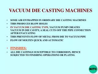
SOME AIR ENTRAPPED IN ORDINARY DIE CASTING MACHINES THIS PRODUCES BLOW HOLES IN VACUUM DIE CASTING TYPE, VACUUM PUMP CREATES VACUUM IN DIE CAVITY, A SEAL CUTS OFF THE PIPE CONNECTION AFTER EVACUATING THIS PREVENTS FLOW OF METAL FROM DIE TO VACUUM PIPE FLOW OF MOLTEN QUICK AND AUTOMATIC FINISHES: ALL DIE CASTINGS SUSCEPTIBLE TO CORROSION, HENCE SUBJECTED TO FINISHING OPERATIONS OR PLATING VACUUM DIE CASTING MACHINES NITC
USE OF RIBS, HUBS, BOSSES MUST BE TO REDUCE WEIGHT, STRENGTHEN THE PART, IMPROVE THE APPEARANCE THICK SECTIONS MAKE DIE HOTTER AND THUS LESSEN DIE LIFE LARGE SECTIONS TO BE COOLED MAY CAUSE POROSITY EXCESSIVE SECTIONAL CHANGES TO BE AVOIDED AVOID UNDERCUTS FILLETS DESIRABLE OVER SHARP EDGES DRAFTS NEEDED ON ALL CASTINGS EJECTOR PINS AT BACK TO AVOID VISIBILITY OF MARKS FLASH NECESSARY , TO BE REMOVED LATER BY TRIMMING DESIGN CONSIDERATIONS NITC
DIE MATERIALS NITC
MAINLY NON-FERROUS CASTINGS WITH PROPERTIES COMPARABLE WITH FORGINGS ZINC ALLOYS:- WIDELY USED ( 70%)- Al 4.1%; Cu MAX 1%, Mg 0.4%; BALANCE ZINC -- PERMITS LONGER DIE LIFE, SINCE TEMP. IS LOW GOOD STRENGTH, Tensile Strength: 300 Kg/cm2 VERY GOOD FLUIDITY, THUS THIN SECTIONS POSSIBLE USES: AUTOMOBILES, OIL BURNERS, FRIDGES, RADIO, TV COMPONENTS, MACHINE TOOLS, OFFICE MACHINERIES DIE CASTING ALLOYS NITC
ALUMINIUM ALLOYS: BY COLD CHAMBER PROCESS- Cu 3 to 3.5%, Si 5 to 11 %, BALANCE Al. LIGHTEST ALLOYS, GOOD CORROSION RESISTANCE, FINE GRAINED STRUCTURE DUE TO CHILLING EFFECT Tensile Strength: 1250 to 2500 Kg/cm2 GOOD MACHINABILITY, SURFACE FINISH USES: MACHINE PARTS, AUTOMOTIVE, HOUSE HOLD APPLIANCES ETC. NITC
COPPER BASED ALLOYS: Cu 57 to 81%;Zn 15 to 40%; SMALL QUANTITIES OF Si, Pb, Sn VERY HIGH TENSILE STRENGTH: 3700 to 6700Kg/cm2; GOOD CORROSION RESISTANCE; WEAR RESISTANCE LOW FLUIDITY, HENCE REDUCED DIE LIFE USES; ELECTRICAL MACHINERY PARTS, SMALLGEARS, MARINE, AUTOMOTIVE AND AIR CRAFT FITTINGS, HARDWARES NITC
MAGNESIUM BASED ALLOYS: LIGHTEST IN DIE CASTING, PRODUCTION COST SLIGHTLY HIGH, Al: 9%; Zn: 0.5%; Mn: 0.5%; Si: 0.5%, Cu:0.3%; REMAINING Mg. USES: IN AIRCRAFT INDUSTRY, MOTOR & ISTRUMENT PARTS, PORTABLE TOOLS, HOUSE HOLD APPLIANCES LEAD & TIN BASED ALLOYS; Lead base: 80% Pb & ; Tin base 75% tin, antimony, copper LIMITED APPLICATIONS. LIGHT DUTY BEARINGS, BATTERY PARTS, X-RAY SHIELDS, LOW COST JEWELLERY, NON-CORROSIVE APPLICATIONS NITC
DEVELOPED IN 1960’S (also called liquid forging) SOLIDIFICATION OF MOLTEN METAL UNDER HIGH PRESSURE (pressure application when liquid partially solidifies 70 to 140 MPa) A COMBINATION OF CASTING & FORGING DIE, PUNCH, EJECTOR PIN PUNCH KEEPS ENTRAPPED GASES IN SOLUTION, RAPID COOLING DUE TO HIGH PRESSURE DIE- METAL INTERFACE PARTS OF NEAR-NET SHAPE MADE, COMPLEX AND FINE SURFACE DETAILS OBTAINED. No riser needed FOR FERROUS & NON FERROUS AUTOMOTIVE WHEELS, SHORT BARRELED CANNONS ETC. SQUEEZE CASTING
1. Pattern (with vent holes) is placed on hollow carrier plate. 2. A heater softens the .003" to .007" plastic film. Plastic has good elasticity and high plastic deformation ratio. 3. Softened film drapes over the pattern with 300 to 600 mm Hg vacuum acting through the pattern vents to draw it tightly around pattern. 4. Flask is placed on the film-coated pattern. Flask walls are also a vacuum chamber with outlet shown. 5. Flask is filled with fine, dry unbonded sand. Slight vibration compacts sand to maximum bulk density. 6. Sprue cup is formed and the mold surface leveled. The back of the mold is covered with unheated plastic film. 7. Vacuum is applied to flask. Atmospheric pressure then hardens the sand. When the vacuum is released on the pattern carrier plate, the mold strips easily. 8. Cope and drag assembly form a plastic-lined cavity. During pouring, molds are kept under vacuum. 9. After cooling, the vacuum is released and free-flowing sand drops away leaving a clean casting, with no sand lumps. Sand is cooled for reuse. V-Process NITC
Benefits Of Using The V-Process: Very Smooth Surface Finish 125-150 RMS is the norm. Cast surface of 200 or better, based on The Aluminum Association of America STD AA-C5-E18. Excellent Dimensional Accuracy Typically +/-.010 up to 1 inch plus +/-.002 per additional inch. Certain details can be held closer. +/-.010 across the parting line. Cored areas may require additional tolerances. Zero Draft Eliminates the need for machining off draft to provide clearance for mating parts and assembly. Provides consistent wall thickness for weight reduction and aesthetic appeal. Allows for simple fixturing for machining and inspection. NITC
Pattern construction becomes more accurate and efficient. Total tolerance range becomes more accurate and efficient. Geometry/tolerance of part is at its simplest form. Draft does not use up tolerance. Design/drafting is less complex. Calculations and depictions related to draft are eliminated. Thin Wall Sections Walls as low as .100 in some applications are possible. Excellent Reproduction Of Details Very small features and lettering are possible. Consistent Quality All molding is semi-automatic. Variable "human factor" has been reduced. Superior Machining Sound metal and no hidden sand in the castings means fewer setups, reduced scrap and longer tool life. Low Tooling Costs NITC
All patterns are made from epoxy, machined plastics, SLA or LDM. There is no need to retool for production quantities. Unlimited Pattern Life Patterns are protected by plastic film during each sand molding cycle. Easy Revisions To Patterns No metal tooling to weld or mill. Great for prototypes. Short-Run Production Capability Excellent for short-run production while waiting for hard tooling. The V-PROCESS method can outproduce traditional prototype methods such as plaster or investment castings. Fast Turnaround From placement of order to sample casting in as little as two to four weeks. NITC
CENTRIFUGAL CASTING AN OVERVIEW • Known for several hundred years. • But its evolution into a sophisticated production method for other than simple shapes has taken place only in this century. • Today, very high quality castings of considerable complexity are produced using this technique. NITC
To make a centrifugal casting, molten metal is poured into a spinning mold. • The mold may be oriented horizontally or vertically, depending on the casting's aspect ratio. • Short, square products are cast vertically while long tubular shapes are cast horizontally. In either case, centrifugal force holds the molten metal against the mold wall until it solidifies. • Carefully weighed charges ensure that just enough metal freezes in the mold to yield the desired wall thickness. • In some cases, dissimilar alloys can be cast sequentially to produce a composite structure. NITC
CENTRIFUGAL CASTINGTRUE- C.I. PIPES, LINERS, BUSHES, CYLINDER BARRELS ETC.SEMI-CENTRE CORE FOR INNER SURFACE- SHAPE BY MOULD AND CORE, MAINLY NOT BY CENRTRIFUGAL ACTION- Eg:FLYWHEELSPRESSURE OR CENTRIFUGAL CASTING- ALSO TERMED AS CENTRIFUGINGFOR NON SYMMETRICAL SHAPES MOULD WITH ANY SHAPE PLACED AT CERTAIN DISTANCE FROM AXIS
SEMI- CENTRE CORE FOR INNER SURFACE- SHAPE BY MOULD AND CORE, MAINLY NOT BY CENRTRIFUGAL ACTION- Eg:FLYWHEELS SPEED OF ROTATION- 60 TO 70 TIMES GRAVITY FOR HORIZONTAL AND INCLINED TYPES ABOVE 100 FOR VERTICAL TYPES. NITC
CENTRIFUGINGPROPERTIES OF CASTING DEPEND ON DISTANCE FROM AXIS SQUEEZE CASTING DIE, PUNCH, EJECTOR PIN PARTS OF NEAR-NET SHAPE MADE, COMPLEX AND FINE SURFACE DETAILS OBTAINED FOR FERROUS & NON FERROUS
+ points: Denser structure, cleaner, foreign elements segregated (inner surface) Mass production with less rejection Runners, risers, cores avoided Improved mechanical properties Closer dimensions possible, less machining Thinner sections possible Any metal can be cast CENTRIFUGAL CASTING NITC
points: Only for cylindrical and annular parts with limited range of sizes High initial cost Skilled labour needed Too high speed leads to surface cracks- (high stresses in the mould ) NITC
For copper alloy castings, moulds are usually made from carbon steel coated with a suitable refractory mold wash. • Molds can be costly if ordered to custom dimensions, but the larger centrifugal foundries maintain sizeable stocks of molds in diameters ranging from a few centimetres to several metres. • The inherent quality of centrifugal castings is based on the fact that most nonmetallic impurities in castings are less dense than the metal itself. Centrifugal force causes impurities (dross, oxides) to concentrate at the casting's inner surface. This is usually machined away, leaving only clean metal in the finished product. • Because freezing is rapid and completely directional, centrifugal castings are inherently sound and pressure tight. • Mechanical properties can be somewhat higher than those of statically cast products. NITC
Centrifugal castings are made in sizes ranging from approximately 50 mm to 4 m in diameter and from a few inches to many yards in length. • Size limitations, if any, are likely as not based on the foundry's melt shop capacity. • Simple-shaped centrifugal castings are used for items such as pipe flanges and valve components, while complex shapes can be cast by using cores and shaped molds. • Pressure-retaining centrifugal castings have been found to be mechanically equivalent to more costly forgings and extrusions. NITC