Finite Element Method Final Project “ Rear Suspension- Double A- Arms”
280 likes | 525 Vues
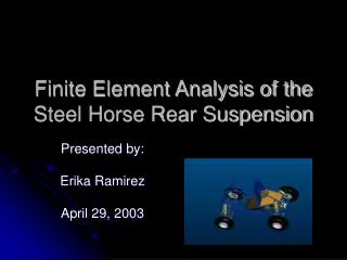
Finite Element Method Final Project “ Rear Suspension- Double A- Arms”. Jaime Taha T. April 29 th 2003. Mini Baja. Competition takes place on a motor cross track. Suspension must React and perform well. Protect the driver from impacts from the rough terrain.

Finite Element Method Final Project “ Rear Suspension- Double A- Arms”
E N D
Presentation Transcript
Finite Element MethodFinal Project“ Rear Suspension-Double A- Arms” Jaime Taha T. April 29th 2003
Mini Baja • Competition takes place on a motor cross track. • Suspension must • React and perform well. • Protect the driver from impacts from the rough terrain. • Be strong enough to survive the track
More pictures. • As we can see, is very feasible that the cars could be hit by another one, or that the tires could hit a rock, bumps, etc.
Problem Statement • The Rear Suspension of the Mini Baja car must be able to withstand the rough terrains associated with the competition’s motor cross track.
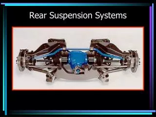
Problem Statement • The Rear Arm Suspension consist of 3 parts: Top Arm, Bottom Arm, and a Hub. • Using the material properties for 4130 Chromoly Steel. • The tubing is a 1” diameter and 0.058” thickness. • In this project the Top arm was analyzed.
2 & 3 Scenarios F=820 lbf FEA Analysis • 3 Scenarios were analyzed (Worst Case scenarios) • Arm Moving • Tire hits a rock, wood, bump, etc. • Tire hit from the side
Impact Force • This force is applied in the second and third scenarios where: • Another car traveling at 30 MPH hits our car and comes to rest at one second • The car hits an object traveling at 30 MPH • Vi=30 MPH, Vf=0 MPH, Time (t) = 1 second, Mass (m) = 600 lb
Stress of the Spring/Damper force only on the Top Arm Weight of the car, acting on both arms Car Frame Reaction force of the weight of the structure acting on both arms Forces acting in the system
Spherical Joints Spring/Damper Spring Force = 175 lb/in Damper Force (C) = 10.2 Lbf Pro E Model Impact Force = 820 lbf Top Arm
Assumptions • Welded zones where neglected • The actuator in the tire simulates the displacement of the tire-arm when the car is driven. • The spring-dash is acting in the as a distributed load (Pro E model image.) • Spherical joints were used where the arm is attached to the car’s structure, also the car frame was assumed that doesn’t move (Car’s frame doesn’t take any load.) • To simulate the impacts in the car, a ramp function was used. • The reaction force of the tire is calculated as a worse case scenario where all the weight of the car is applied only in one tire 600 lb, as a distributed force.
Stress Analysis 0.03ft Max. Value = 7.46e8 Value in a specific point = 6.03e8 Pa Stress Analysis 0.02ft Max. Value = 8.6 e8 Value in a specific point = 7.03e8 Pa Finite Element ModelingScenario 1 – Arm moving. • Stress Analysis
FS-0.03 FS-0.02 Finite Element ModelingScenario 1 – Arm moving. • Factor of Safety FS-0.03 - Front (above) and Back (below) views of Factor of Safety (Mesh size of 0.03 ft) FS-0.02 - Front (above) and Back (below) views of Factor of Safety (Mesh size of 0.02 ft)
Finite Element ModelingScenario 2 – Tire hits a rock, wood, bump, etc. • Using 0.02 ft. Mesh Max. Value = 8.62e8 Pa Value in a specific point = 6.71e8 Pa
Finite Element ModelingScenario 2 – Tire hits a rock, wood, bump, etc. • Using 0.03 ft. Mesh Max. Value = 7.68e8 Pa Value in a specific point = 4.66e8 Pa
Finite Element ModelingScenario 2 – Tire hits a rock, wood, bump, etc. • Using 0.04 ft. Mesh Max. Value = 1.42e9 Pa Value in a specific point = 1.12e9 Pa
FS – 0.02ft FS – 0.03ft Finite Element ModelingScenario 2 – Tire hits a rock, wood, bump, etc. • Factor of Safety
Finite Element ModelingScenario 2 – Tire hits a rock, wood, bump, etc. • Simulation of stress analysis in the tire-arm with movement Change in stresses when object moves Movement and stresses
Finite Element ModelingScenario 3 – Tire hit from the side. • Using 0.03 ft. Mesh Max. Value = 6.7e8 Pa Value in a specific point = 5.06e8 Pa
Finite Element ModelingScenario 3 – Tire hit from the side. • Using 0.02 ft. Mesh Max. Value = 1.27e9 Pa Value in a specific point = 8.25e8 Pa
Finite Element ModelingScenario 3 – Tire hit from the side. • Simulation of stress analysis in the tire-arm with movement Movement and stresses Change in stresses when object moves
Previous Possible Alternative Improvement - Pro E Drawings. • Adding the pipe showed, the stresses concentration could be distributed.
Point2 …Cont’ • Comparing the 1st case scenario: • The addition of the pipe decreases the stresses and also distribute the stress concentration Stress Analysis 0.03ft Max. Value = 7.46e8 Pa Value in a specific point = 6.03e8 Pa Stress Analysis 0.03ft Max. Value = 1.4e8 Pa Value in a specific point1 = 2.9e7 Pa Value in a specific point2 = 1.1e8 Pa
Actual part Modify part (addition of a pipe) Finite Element ModelingScenario 1 – Arm moving. • As explained before, with the addition of the pipe, the stress concentration decrease and also was distributed (Mesh size 0.03 ft). An increase is notable in the new model (right image) in the Factor of Safety from 0.54 to 3.46.
Actual part Modify part (addition of a pipe) Finite Element ModelingScenario 3 – Tire hit from the side. • In this scenario, the addition of the pipe also affect the factor of safety, as we can see the red zones from the figures.
Problems/Comments while doing my project. • Pro E • Drawings • Cut the inside of the pipes • Verify units • Geometry settings/connection to Visual Nastran (Why doesn’t work???)
Problems/Comments while doing my project. • Visual Nastran • Meshing the part – “play” with the mesh size. • The use of H-Adaptivity is hard to run it because thin structure and other elements (such as spring, actuator, etc) • Verify the restraints, forces, springs, actuators, motor, etc. • Verify Joints (also is very important to verify the dynamic loadings) • While running the FEA with motion there’s no way to stop it.
Comments • 3 scenarios were analyzed • H-Adaptivity was not used because of the complexity of the part and the thickness. • A possible alternative of adding a pipe between the arms with the purpose of decrease stress concentration and also distribute the load. In fact the results showed that by adding the pipe, the stresses slightly reduce • FEA is a time consuming process, it can be improve if the analysis is run on a more capable computers. • Further work: • Verify the pipes diameter/thickness and do FEA
Acknowledgements Dr. Arturo Fuentes Mini Baja Team Classmates