Download
1 / 19
190 likes | 383 Vues
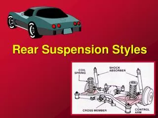
Finite Element Analysis of the Steel Horse Rear Suspension. Presented by: Erika Ramirez April 29, 2003. Problem Statement. The rear suspension of any mini baja car must be able to withstand the rough terrains associated with the competition’s motor cross track.

E N D
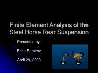
Finite Element Analysis of the Steel Horse Rear Suspension Presented by: Erika Ramirez April 29, 2003
Problem Statement • The rear suspension of any mini baja car must be able to withstand the rough terrains associated with the competition’s motor cross track. • The objective of this project is to successfully analyze the rear suspension with an impact load at the rear of the tire.
Problem Formulation • The rear suspension to be analyzed is a single a-arm. It is made out of 4130 Chromoly tubing with an outer diameter of 1” and thickness of .058”.
Impact Force Impact Force Another car traveling at 30 mph hits our car and comes to rest at one second or the car hits an object traveling at 30MPH form the side: Vi=30 MPH Vf=0 MPH t=1s m=600lb Vf=Vi+at a(impact)=Vf-Vi/t F=m*a(imp) F = 820 lbf
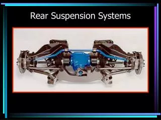
Worst Case Scenario • The car lands in one tire. • Weight of the vehicle (600 lbs) • The tire hits a rock, bump, etc. • Use the 820 lbf load • Use an Actuator to model the motor – cross track
Material Properties • Density • .284 lb/in^3 • Modulus of Elasticity • 205 GPa • Yield Stress • 8e8 Pa • UTS • 9.65e9 Pa
Pro-E Model SPRING/DAMPER (SHOCK) – 175 lb/in and C=10.2 IMPACT FORCE = 820 lb REVOLUTE JOINTS ACTUATOR
Finite Element Modeling (Stresses) • Concentration of Stresses located at the revolute joints.
Displacements Max Displacement occurs at the Hub tabs near the tire – also at one of the revolute joints.
Making the ends .01” thicker Von Misses Stresses
Comparing Stresses The Maximum Principle Stresses are greatly reduced by making the revolute joints .01 thicker.
Comparing Displacements Displacements were increased a little from .75891 to .82149 in.
Von Misses Stresses Von Misses stresses were also reduced.
Comparing Factor of Safety Minimum Factor of Safety was increased – and there are less areas of concern.
Comments / Summary • H-Adaptivity was not used because of the complexity of the part. • The Mesh size used was .02 Feet, this was done after converging on the same maximum value of stresses (no significant change for a smaller mesh size). • A simple way to reduce the stress concentrations would be to introduce more material on the revolute ends.