CHECK VALVES
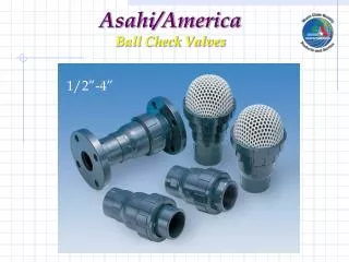
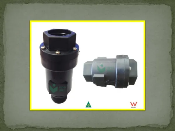
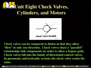
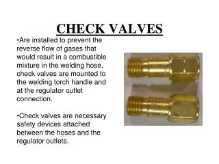
CHECK VALVES. Are installed to prevent the reverse flow of gases that would result in a combustible mixture in the welding hose, check valves are mounted to the welding torch handle and at the regulator outlet connection.

CHECK VALVES
E N D
Presentation Transcript
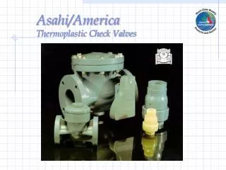
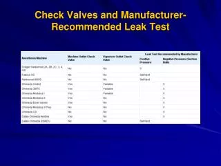
CHECK VALVES • Are installed to prevent the reverse flow of gases that would result in a combustible mixture in the welding hose, check valves are mounted to the welding torch handle and at the regulator outlet connection. • Check valves are necessary safety devices attached between the hoses and the regulator outlets.
TORCH HANDLE • The torch handle is probably the most frequently used item in a welding shop. • Cutting attachments, welding tips and heating nozzles are all connected to the torch handle. • Always inspect the torch handle head, valves and hose connections for oil, grease or damaged parts. • Oxygen connection is usually marked “OXY” • Acetylene connection is usually marked “FUEL”
TORCH HANDLE Identification • Torch Head • Barrel • Torch Body • Oxygen Control Valve • Acetylene Control Valve
WELDING NOZZLE • Inspect the cone end, coupling nut, o-rings and welding nozzle for damage, oil or grease. • Connect the welding nozzle to the torch handle. Tighten the coupling nut hand-tight only. Wrench tightening may damage o-rings and create a faulty seal allowing leaks. • Note- There must always be two o-rings on the cone end of the nozzle. The absence or damage of either of these o-rings allows premixing and leaks of oxygen and acetylene.
CUTTING HEAD ATTACHMENT Mixing Chamber Cutting Oxygen (Top) Coupling Nut VICTOR High-Pressure Cutting Oxygen Lever SMITH Pre-heat Oxygen (middle) Pre-Heat Oxygen Control Valve Pre-heat Acetylene (bottom)
CUTTING TIP • Preheat Orifices • The Mixture of Oxygen and Acetylene Gas (6 surrounding holes) • Oxygen Cutting Jet Orifice • Pure Oxygen (Center Hole)
Oxygen Regulator- Cylinder Pressure Gaugeright side – closest to cylinder valve
Oxygen Regulator- Working Gaugeleft side- above green hose connection*NEVER EXCEED 40 PSI
Acetylene Regulator- Cylinder Pressure Gaugeright side- closest to cylindervalve
Acetylene Regulator- Working Gaugeleft side- above red hose connection*NEVER EXCEED 15 PSI
Protective Wear • Shade #5 Goggles or Glasses • Friction Lighter (striker) • Leather Gloves & Coveralls • Leather Boots