Download
1 / 42
450 likes | 711 Vues
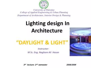
Lighting design In Architecture. “ DAYLIGHT & light”. Instructor: M Sc. Eng. Nagham Ali Hasan. 3 rd lecture- 2 nd semester 2008/2009. INVERSE SQUARE LAW.

E N D
Lighting design In Architecture “DAYLIGHT & light” Instructor: M Sc. Eng. Nagham Ali Hasan 3rd lecture- 2nd semester 2008/2009
INVERSESQUARE LAW • The illuminance on a surface which is produced by a single light source, varies inversely as the square of the distance from the source. • This is known as the INVERSE SQUARE LAW and is shown by the expression:
If the distance is doubled between the light source and surface, the illuminance E will fall to one quarter of the previous value. • Although the illuminated area will increase in size, the illuminance on the surface however will decrease accordingly. • This effect can be demonstrated by shining a torchlight directly onto a flat surface and observing the increased area of light when the torch is moved further away from the surface.
COSINELAW If a beam of light from a lamp hits a surface at an angle, the illuminated area increases but the illuminance on the surface is lower than when the light is pointed directly at the surface. This effect can be demonstrated by holding a torchlight at an angle to a surface, rather than directly at the surface, and observing the increased illuminated area. The illuminance at a point on the surface will now be reduced by a factor of the cosine of the angle. This is known as the COSINE LAW and is shown by the expression:
The COSINE LAW is illustrated in the Figure. A 500 cd incandescent lamp is fixed at a height of 2 metres directly above a long bench, and the value of illuminance at point P is to be determined.
Figure shows two luminaires, LI and L2, mounted 5 metres apart. Each lamp inside the luminaires emits 600 cd in all directions. The values of illuminance at points PI, P2 and P3 are to be determined..
Example twoThe forecourt of a building is to be illuminated by four floodlights , mounted on 6 meter high poles. A pole is positioned at each corner of the square forecourt which measures 20 m x 20 m. Each lamp and luminaire combination produces a luminous intensity of2500 cd. Illuminance levels . are to be determined at: - (a)' the base of each pole, P1 (b) the centre of the forecourt, P2 (c) a point on the ground midway between each pole, P3
To determine distance dl, distance bl must be calculated first
To determinedistance d1, distance b1 must be calculated first
Maximum spacing information for symmetrical luminaires may be shown in the photometric data as SHR MAX, meaning space-height ratio maximum. • For example, if a SHR MAX 1.4is stated for the luminaire in last Figure and the mounting height of luminaire above the working plane is 1.9 m then the maxImum spacing on either direction can be calculated as follows:
If the spacing-height ratio is exceeded then there will be areas between luminaires which will have a serious reduction of illuminance.
In the case of fluorescent luminaires that do not have an axially-symmetrical intensity distribution, maximum spacing infonnation stated in the photometric data may indicate: Uniformity of illuminance
In these circumstances, three conditions must be complied with: • 1- The spacing in the transverse direction (SHR TR) must not exceed SHR MAX TR stated. • 2- The spacing in the axial direction (SHR AX) must not exceed the SHR MAX stated. • 3- The actual spacings in the two direction (SHR AX & SHR TR) when multiplied together must not exceed ( SHR MAX ) 2