Introduction to Networking
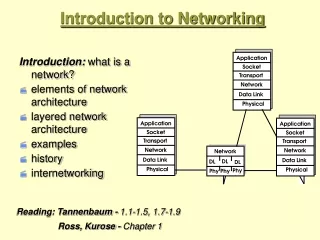
Introduction to Networking. Internet: Example. Click -> get page Specifies - protocol (http) - location (www.cnn.com). Internet: Locating Resource. www.cnn.com name of a computer Implicitly also a file Map name to IP address DNS. cnn.com?. cnn.com?. host. local. com. a.b.c.d.

Introduction to Networking
E N D
Presentation Transcript
Internet: Example • Click -> get page • Specifies - protocol (http) - location (www.cnn.com)
Internet: Locating Resource • www.cnn.com • name of a computer • Implicitly also a file • Map name to IP address • DNS cnn.com? cnn.com? host local com a.b.c.d a.b.c.d
Internet: Connection • Http sets up a connection (tcp) • between the host and cnn.com to transfer the page • The connection transfers page as a byte stream • without errors: flow control + error control Host www.cnn.com Connect OK Get page Page; close
Internet: End-to-end • Byte stream flows end to end across many links/switches: • routing (+ addressing) • That stream is regulated and controlled by both ends: • retransmission of erroneous or missing bytes; flow control
Internet: Packets • The network transports bytes grouped into packets • Packets are “self-contained”; routers handle them 1 by 1 • The end hosts worry about errors and pacing • Destination sends ACKs; Source checks losses
Internet: Bits • Equipment in each node sends packets as string of bits • That equipment is not aware of the meaning of the bits • Frames (packetizing) vs. streams
Internet: Points to remember • Separation of tasks • send bits on a link: transmitter/receiver [clock, modulation,…] • send packet on each hop [framing, error detection,…] • send packet end to end [addressing, routing] • pace transmissions [detect congestion] • retransmit erroneous or missing packets [acks, timeout] • find destination address from name [DNS] • Scalability • routers don’t know full path • names and addresses are hierarchical
Internet : Challenges • Addressing ? • Routing ? • Reliable transmission ? • Interoperability ? • Resource management ? • Quality of service ?
Concepts at heart of the Internet • Protocol • Layered Architecture • Packet Switching • Distributed Control • Open System
Protocol • Two communicating entities must agree on: • Expected order and meaning of messages they exchange • The action to perform on sending/receiving a message • Asking the time
Layered Architectures • Human beings can handle lots of complexity in their protocol processing. • Ambiguously defined protocols • Many protocols all at once • How computers manage complex protocol processing? • Specify well defined protocols to enact. • Decompose complicated jobs into layers; • each has a well defined task
Layered Architectures • Break-up design problem into smaller problems • More manageable • Modular design: easy to extend/modify. • Difficult to implement • careful with interaction of layers for efficiency
Layered Architecture users network Applications Web, e-mail, file transfer, ... Middleware Reliable/ordered transmission, QOS, security, compression, ... Routing End-to-end transmission, resource allocation, routing, ... Physical Links Point-to-point links, LANs, radios, ...
The OSI Model • Open Systems Interconnect model is a standard way of understanding conceptual layers of network comm. • This is a model, nobody builds systems like this. • Each level provides certain functions and guarantees, and communicates with the same level on remote notes. • A message is generated at the highest level, and is passed down the levels, encapsulated by lower levels, until it is sent over the wire. • On the destination, it makes its way up the layers,until the high-level msg reaches its high-level destination.
OSI Levels Node A Application Node B Application Presentation Presentation Transport Transport Network Network Data Link Data Link Physical Physical Network
OSI Levels • Physical Layer: electrical details of bits on the wire • Data Link: sending “frames” of bits and error detection • Network Layer:” routing packets to the destination • Transport Layer: reliable transmission of messages, disassembly/assembly, ordering, retransmission of lost packets • Session Layer; really part of transport, typ. Not impl. • Presentation Layer: data representation in the message • Application: high-level protocols (mail, ftp, etc.)
Internet protocol stack users network Application HTTP, SMTP, FTP, TELNET, DNS, … Transport TCP, UDP. Network IP Physical Point-to-point links, LANs, radios, ...
Air travel Passenger Origin Passenger Destination Ticket (purchase) Ticket (complain) Baggage (check) Baggage (claim) Gates (load) Gates (unload) Runway (take off) Runway (landing) Airplane routing
Protocol stack user X English user Y e-mail client e-mail server SMTP TCP server TCP server TCP IP server IP IP server IEEE 802.3 standard ethernet driver/card ethernet driver/card electric signals
Protocol interfaces user X user Y e-mail client e-mail server TCP server s = open_socket(); socket_write(s, buffer); … TCP server IP server IP server ethernet driver/card ethernet driver/card
Addressing • Each network interface has a hardware address • Multiple interfaces multiple addresses • Each application communicates via a port • Port is a logical connection endpoint • Allows multiple local applications to use network resources • Up to 65535 • < 1024 : used by privileged applications • 1024 ≤ available for use ≤ 49151 • 49152 ≤ Dynamic ports/private ports ≤ 65535 • http ports 80 and 8080 • telnet 23, ftp 21, etc • Think of a telephone network …
Addressing and Packet Format • The ``Data'' segment contains higher level protocol information. • Which protocol is this packet destined for? • Which process is the packet destined for? • Which packet is this in a sequence of packets? • What kind of packet is this? • This is the stuff of the OSI reference model. Start (7 bytes) Destination (6) Source (6) Length (2) Msg Data (1500) Checksum (4)
Ethernet packet dispatching • An incoming packet comes into the Ethernet controller. • The Ethernet controller reads it off the network into a buffer. • It interrupts the CPU. • A network interrupt handler reads the packet out of the controller into memory. • A dispatch routine looks at the Data part and hands it to a higher level protocol • The higher level protocol copies it out into user space. • A program manipulates the data. • The output path is similar. • Consider what happens when you send mail.
To: Dad To: Dad Hi Dad. Hi Dad. To: Dad To: Dad Hi Dad. Hi Dad. To: Dad To: Dad Hi Dad. Hi Dad. Example: Mail Hi Dad. Hi Dad. Mail Composition And Display SrcAddr: 128.95.1.2 DestAddr: 128.95.1.3 SrcPort: 110, DestPort: 110Bytes: 1-20 SrcAddr: 128.95.1.2 DestAddr: 128.95.1.3 SrcPort: 110, DestPort: 110Bytes: 1-20 Mail Transport Layer User Kernel Network Transport Layer SrcEther: 0xdeadbeef DestEther: 0xfeedface SrcEther: 0xdeadbeef DestEther: 0xfeedface Link Layer SrcAddr: 128.95.1.2 DestAddr: 128.95.1.3 SrcPort: 100 DestPort: 200Bytes: 1-20 SrcAddr: 128.95.1.2 DestAddr: 128.95.1.3 SrcPort: 100 DestPort: 200Bytes: 1-20 Network
Protocol encapsulation user X user Y “Hello” e-mail client e-mail server “Hello” TCP server TCP server “Hello” IP server IP server “Hello” ethernet driver/card ethernet driver/card “Hello”
End-to-End Argument • What function to implement in each layer? • Saltzer, Reed, Clarke 1984 • A function can be correctly and completely implemented only with the knowledge and help of applications standing at the communication endpoints • Argues for moving function upward in a layered architecture • Should the network guarantee packet delivery ? • Think about a file transfer program • Read file from disk, send it, the receiver reads packets and writes them to the disk
End-to-End Argument • If the network guaranteed packet delivery • one might think that the applications would be simpler • No need to worry about retransmits • But need to check that file was written to the remote disk intact • A check is necessary if nodes can fail • Consequently, applications need to perform their retransmits • No need to burden the internals of the network with properties that can, and must, be implemented at the periphery
End-to-End Argument • An Occam’s razor for Internet design • If there is a problem, the simplest explanation is probably the correct one • Application-specific properties are best provided by the applications, not the network • Guaranteed, or ordered, packet delivery, duplicate suppression, security, etc. • The internet performs the simplest packet routing and delivery service it can • Packets are sent on a best-effort basis • Higher-level applications do the rest
Two ways to handle networking • Circuit Switching • What you get when you make a phone call • Dedicated circuit per call • Packet Switching • What you get when you send a bunch of letters • Network bandwidth consumed only when sending • Packets are routed independently
Circuit Switching • End-to-end resources reserved for “call” • Link bandwidth, switch capacity • Dedicated resources: no sharing • Circuit-like (guaranteed) performance • Call setup required
Packet Switching • Each end-to-end data stream divided into packets • User’s packets share network resources • Compared to dedicated allocation • Each packet uses full link bandwidth • Compared to dividing bandwidth into pieces • Resources are used as needed • Compared to resource reservation • Resource contention: • Aggregate demand can exceed amount available • Congestion: packets queue, wait for link use • Store and forward: packets move one hop at a time • Transmit over link • Wait turn at next link
Routing • Goal: move data among routers from source to dest. • Datagram packet network: • Destination address determines next hop • Routes may change during session • Analogy: driving, asking directions • No notion of call state • Circuit-switched network: • Call allocated time slots of bandwidth at each link • Fixed path (for call) determined at call setup • Switches maintain lots of per call state: resource allocation
Packet vs. Circuit Switching • Reliability: no congestion, in-order data in circuit-switch • Packet switching: better bandwidth use • State, resources: packet switching has less state • Good: less control plane processing resources along the way • More data plane (address lookup) processing • Failure modes (routers/links down) • Packet switch reconfigures sub-second timescale • Circuit switching: more complicated • Involves all switches in the path
A small Internet W b,e4 w,e5 B V Scenario: A wants to send data to B. R r3 r2,e2 r1,e1 a,e3 A
Packet forwarding Host A Host B Router R Router W HTTP HTTP TCP TCP IP IP IP IP eth link link eth ethernet ethernet
What is purpose of this layer? • Physically encode bits on the wire • Link = pipe to send information • E.g. point to point or broadcast • Can be built out of: • Twisted pair, coaxial cable, optical fiber, radio waves, etc • Links should only be able to send data • Could corrupt, lose, reorder, duplicate, (fail in other ways)
How to connect routers/machines? • WAN/Router Connections • Commercial: • T1 (1.5 Mbps), T3 (44 Mbps) • OC1 (51 Mbps), OC3 (155 Mbps) • ISDN (64 Kbps) • Frame Relay (1-100 Mbps, usually 1.5 Mbps) • ATM (some Gbps) • To your home: • DSL • Cable • Local Area: • Ethernet: IEEE 802.3 (10 Mbps, 100 Mbps, 1 Gbps, 10Gbps) • Wireless: IEEE 802.11 b/g/a (11 Mbps, 22 Mbps, 54 Mbps)
Link level Issues • Encoding: map bits to analog signals • Framing: Group bits into frames (packets) • Arbitration: multiple senders, one resource • Addressing: multiple receivers, one wire
Encoding • Map 1s and 0s to electric signals • Simple scheme: Non-Return to Zero (NRZ) • 0 = low voltage, 1 = high voltage • Problems: • How to tell an error? When jammed? When is bus idle? • When to sample? Clock recovery is difficult. • Idea: Recover clock using encoding transitions 1 0 1 1 0
0 1 1 0 Manchester Encoding • Used by Ethernet • Idea: Map 0 to low-to-high transition, 1 to high-to-low • Plusses: can detect dead-link, can recover clock • Bad: reduce bandwidth, i.e. bit rate = ½ baud rate • If wire can do X transition per second?
Framing • Why send packets? • Error control • How do you know when to stop reading? • Sentinel approach: send start and end sequence • For example, if sentinel is 11111 • 11111 00101001111100 11111 10101001 11111 010011 11111 • What if sentinel appears in the data? • map sentinel to something else, receiver maps it back • Bit stuffing
Example: HDLC • Same sentinel for begin and end: 0111 1110 • packet format: • Bit stuffing • Sender: If 5 1s then insert a 0 • Receiver: if 5 1s followed by a 0, remove 0 • Else read next bit • Packet size now depends on the contents 0111 1110 header data CRC 0111 1110 0111 1110 0111 1101 0 0111 1101 0 0111 1110
Arbitration • One medium, multiple senders • What did we do for CPU, memory, readers/writers? • New Problem: No centralized control • Approaches • TDMA: Time Division Multiple Access • Divide time into slots, round robin among senders • If you exceed the capacity do not admit more (busy signal) • FDMA: Frequency Division Multiple Access (AMPS) • Divide spectrum into channels, give each sender a channel • If no more channels available, give a busy signal • Good for continuous streams: fixed delay, constant data rate • Bad for bursty Internet traffic: idle slots
Ethernet • Developed in 1976, Metcalfe and Boggs at Xerox • Uses CSMA/CD: • Carrier Sense Multiple Access with Collision Detection • Easy way to connect LANs Metcalfe’s Ethernet sketch
CSMA/CD • Carrier Sense: • Listen before you speak • Multiple Access: • Multiple hosts can access the network • Collision Detection: • Can make out if someone else started speaking Older Ethernet Frame
CSMA Wait until carrier free
CSMA/CA Garbled signals If the sender detects a collision, it will stop and then retry! What is the problem?
No Yes attempts < 16 attempts == 16 CSMA/CD Packet? Sense Carrier Detect Collision Send Discard Packet Jam channel b=CalcBackoff(); wait(b); attempts++;