Download
1 / 26
260 likes | 421 Vues
GROUNDING SYSTEM OF HV/MV SUBSTATIONS FORMED THROUGH CABLE LINES WITH INSULATED METAL SHEATH. OUTHGOING MV CABLE LINE WITH INSULATED METAL SHEAT. EQUIVALENT CIRCUIT FORMED THROUGH THE METAL SHEATS OF A CABLE LINE WITH INSULATED METAL SHEAT. APPLIED NOTATIONS HAVE THE FOLLOWING MEANING.

E N D
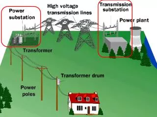
GROUNDING SYSTEM OF HV/MV SUBSTATIONS FORMED THROUGH CABLE LINES WITH INSULATED METAL SHEATH
EQUIVALENT CIRCUIT FORMED THROUGH THE METAL SHEATS OF A CABLE LINE WITH INSULATED METAL SHEAT
ANALYTICAL EXPRESSION FOR GROUNDING IMPEDANCE AT THE BEGINNING OF THE CABLE LINE
ANALYTICAL EXPRESSION FOR THE ACTIVE CABLE LINE LENGTH AND FOR ESTIMATION OF THE AREA COVERED BY THE SPONTANEOUSLY FORMED GROUNDING SYSTEM L’a- active cable line lengthexpressed in relation to the length of average cable line section.
ANALYTICAL EXPRESSION FOR THE CASE WHEN THE FIRST LINE SECTION IS SIGNIFICANTLY DIFFERENT IN COMPARISON WITH THE AVERAGE ONE
ACTIVE LENGTH AND GROUNDING IMPEDANCE OF THE CABLE LINE AS A FUNCTION OF THE GROUNDING IMPEDANCE OF THE SUPPLIED MV/LV SUBSTATIONS
CABLE LINES BELONGING TO ONE OF THE PRIMARY DIRECTIONS AND THEIR SIMPLIFICATION USED IN THE PROCEDURE OF METHOD DEVELOPMENT
ANALYTICAL EXPRESSIONS FOR THE GROUNDING SYSTEM IMPEDANCE AND FOR THE TRANSFERRED POTENTIAL
ADDITIONAL NUMERICAL DATA NECESSARY FOR THE USAGE OF THE PRACTICAL EXAMPLE CONSIDERED IN THE FORMER CASE • total length of each of the cable lines is 4 km • - each line supplies nine 10/0.4 kV substations • - value of the grounding impedance |Zt| is: 1.0 Ω. • self-impedance of tree cable line metal sheaths: • (0.100 + j 0.135) Ω.
TESTING AND EVALUATING OF GROUNDING SYSTEM FOR SUBSTATIONS LOCATED IN URBAN AREAS
FIRST CASE:TEST CURRENTCIRCULATES THROUGH THEENTIRE FEEDING LINE LENGTH
SECOND CASE:TEST CURRENT PASSES ONLY THROUGH THE FEEDING LINE SECTION BETWEEN TESTED AND THE NEAREST TRANSIT SUBSTATION
GEOMETRICAL SHAPE AND SPACE DISPOSITIONOF THE FICTITIOUS CONDUCTOR
CONCLUSIONS • Presented analytical procedure enables observing the whole grounding problem of distribution HV/MV substations into an realistic frame work. • It was shown that the part of the ground fault current passing through the earth is dramaticaly smaller than it was considered until recently. • 3. General conditions for solving grounding problem of distribution HV/MV substations located in urban and suburban areas are much better than it was considered until recently.
REFERENCES 1. Lj. Popović: ”Proximity effect between an earthing grid and external electrodes in an earthing system of high-voltage installations”, IEE Proceedings, Vol. 133, Part C, No. 6, September 1986, pp. 346-352. 2. Lj. Popović: “Potential Distribution Along External Electrodes of a High Voltage Installation Grounding System”, IEEE Transactions on Power Delivery, Vol. 3, No. 4, October 1988, pp. 1580-1587. 3. Lj. Popović: “General Equations of the Line Represented by Discrete Parameters; Part I: Steady State”, IEEE Transactions on Power Delivery, Vol. 6, No. 1, January 1991, pp. 295-301. 4. Lj. Popović: “Practical method for the analysis of eathing systems with long external electrodes”, IEE Proceedings-C, Vol. 140, No. 3, May 1993, pp. 213-220. 5. Lj. Popovic: ”Testing and evaluating grounding systems for substations located in urban areas”, IETGeneration, Transmission and Distribution (DOI: 10.1049/iet-gtd 2009.0665). 6. Lj. Popovic: ”Comparative analysis of grounding systems formed by MV cable lines with either uninsulated or insulated metal sheath(s)”, Electric Power System Research (DOI: 10.1016/j.epsr.2010.10.001). 7. Lj. Popovic: ”Active length of cable lines with uncoated metal sheaths as long grounding conductors”, European Transaction on Electrical Power (DOI: 10.1002/etep.555).