Download
1 / 18
190 likes | 332 Vues
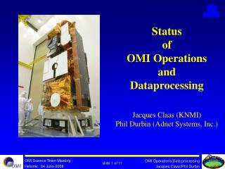
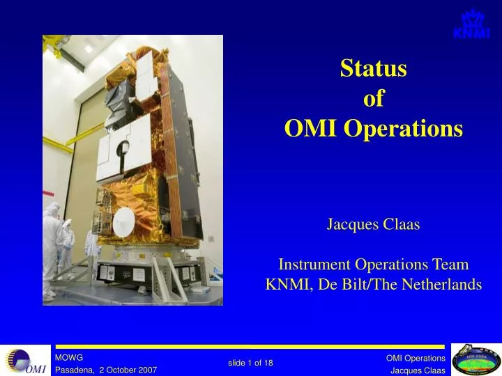
Status of OMI Operations Jacques Claas Instrument Operations Team KNMI, De Bilt/The Netherlands. Instrument status. Instrument performance is excellent but …… No anomalies since the FMM anomaly on Feb 28 th , 2006 CCD temperatures are very stable

E N D
Statusof OMI Operations Jacques ClaasInstrument Operations TeamKNMI, De Bilt/The Netherlands
Instrument status • Instrument performance is excellent but …… • No anomalies since the FMM anomaly on Feb 28th, 2006 • CCD temperatures are very stable • The thermal settings still have their initial values • There has been no data loss during the past year OMI flight model
FMM behaviour • FMM anomaly on Feb 28th, 2006 • Despite detailed analysis, cause not found • A decision was made to change the way the FMMis operated: avoid bouncing against the calibrationend-stop • The FMM is operated by means ofStored Instruction Sequences (SISs) • 4 out of 6 SISs have been modified so far to avoid FMM bouncing. • Results so far:- when using the old SISs, the FMM always shows bouncing behaviour (as expected)- when using the new SISs, the FMM never shows bouncing behaviour (as expected) Assembling the FMM
Operations status • Monitoring all OMI engineering parameters has been fully automated on the OSIPS. • A PGE running on the OSIPS is checking if parameter trends are developing. • Successfully started using the remote Online system • A web interface has been developed giving access to all possible instrument and operations information:www.knmi.nl/omi • Detailed comments have been provided on the impact of the AURA Re-Phasing on OMI Operations. Example of monitoring engineering parameters on OSIPS
Life-Limited Items Budget (Sep 19) Example of information provided via web
CCD row anomaly (1/10) • All OMI L0 data have been reprocessed to L1b data. • The new Collection 3 L1b data replace the old ECS2 L1b data. • Due to the highly improved quality of the new L1b data, an anomaly has been discovered. • The anomaly shows up as deviations in observed radiance for specific CCD rows. OMI detector module with CCD
χ2 plot of Ozone column DOAS fit using old ECS2 L1b data CCD row anomaly (2/10)
χ2 plot of Ozone column DOAS fit using new Collection 3 L1b data CCD row anomaly (3/10)
Performing super zoom-in measurements CCD row anomaly (4/10)
Result of super zoom-in measurements:mean off all VIS images (day part of orbit) CCD row anomaly (5/10) reference box anomaly box
Result of super zoom-in measurements: mean VIS radiance for the “anomaly box” as function of time CCD row anomaly (6/10)
Result of super zoom-in measurements:mean VIS radiance for the “anomaly box” as function of time CCD row anomaly (7/10)
Result of super zoom-in measurements:mean VIS radiance for the “reference box” as function of time CCD row anomaly (8/10)
A few analysis results so far: CCD row anomaly (9/10) • Row anomaly shows up in both VIS and UV2, not in UV1. • Row anomaly only observed for radiance measurements, not for irradiance (sun) or calibration measurements. • The anomaly is observed as a 20-30% signal decrease under illuminated conditions in the level-1b data. • The anomaly is observed as a signal increase when the detector is not illuminated directly, but when the satellite is illuminated by sun / earth light. This signal increase is only observed near the north pole, when the sun light directly illuminates the OMI instrument. The signal increase is not observed near the south pole, when OMI is shadowed from direct sun light illumination by the Aura spacecraft. • The CCDs and related read-out electronics can be ruled out as anomaly cause. • There is a strong quantitative change in the anomaly behaviour during the June 25th - 27th 2007 period.
A few of the main questions that need to be answered: CCD row anomaly (10/10) • Can the row anomaly be caused by a blocking object? • Is this blocking object definitely outside the OMI housing? • Is there a correlation between the row anomaly change during the June 25th – 27th 2007 period and a status change (optical, thermal …?) of the other AURA instruments or the S/C itself? • Is there a correlation between the row anomaly and S/C maneuvers?
OMIelectronics assembly Interface Adapter Module (IAM) OMIoptical assembly
OMI optical assembly with nadir aperture Direction corresponding with anomaly row