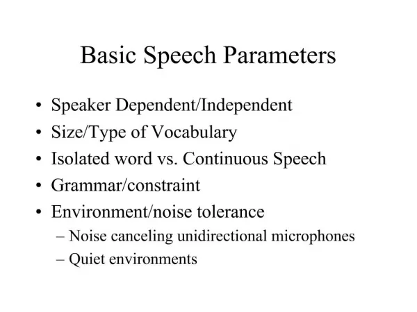
Definition of Basic ADC Parameters
Systematization of Parameters. Parameters according to their form:Point

Definition of Basic ADC Parameters
E N D
Presentation Transcript
1. Definition of Basic ADC Parameters J�n �ALIGA
Dept. of Electronics and Telecommunications
Technical University of Ko�ice
Slovak Republic
2. Systematization of Parameters Parameters according to their form:
Point � a single number, e.g. input range, nominal number of bits, max. DNL, max INL, �
Function � dependence (vector) something on something, e.g. T[k], DNL[k], INL[k], �
Parameters according to their relation to the dynamic effect in ADC (dependency on a frequency or time):
Static or quasistatic � tested by static or slowly changing signal (e.g. DC signal or a low frequency sinewave), e.g. ADC offset and gain, INL[k], DNL[k], �
Dynamic � expressing ADC behavior for quickly changing signals � usually a dependency of parameter on frequency, e.g. effective number of bits (f), �
Parameters according the part of ADC where they are used:
Input, e.g. input range, input impedance, �
Output, e.g. ADC output code, output logic levels, �
Transfer, e.g. INL, DNL, ENOB, THD, SINAD, SNR, �
�
3. Deterministic Versus Probabilistic ADC Transfer Model Deterministic model
4. Parameters directly derived from ADC transfer characteristic 1
5. Parameters directly derived from ADC transfer characteristic 2 Transfer characteristics (ideal=nominal and real TC) � relations between input analog signal value and output digital codes (deterministic and stochastic models)
Straight lines (ideal=nominal and real) � approximation of transfer characteristic by a line based on:
Linking minimum and maximum (end points) in TC
Least square fit
Monotonicity � the higher input signal, the higher ADC output code � if not => error.
6. Parameters directly derived from ADC transfer characteristic 3 Missing code � a code that is never (at any input signal) on the ADC output.
Gain � the slope of real straight line
Gain error � the difference in slopes of nominal and real straight lines
Offset error � the shift of real straight line in comparison with the nominal straight line
7. Parameters directly derived from ADC transfer characteristic 4 Code transition levels T[k] � the levels of input signal where the output code is changing from k-1 to k and their probabilities are the same and equal to 0.5.
Hysteresis - The maximum difference in values of a code transition level, when the transition level is approached by a changing input signal from either side of the transition.
Code bin width W[k] � the difference between T[k-1] and T[k]. The value is constant (Q) for equivalent linear (nominal) ADC � usually also called quantisation step = it is the synonym of the least significant bit (LSB).
8. ADC nonlinearities Nonlinearity (very important) � the difference of real transfer characteristic from the real straight line, i.e the code bin widths are not constant. It is usually indicated by functional parameters as differential and integral nonlinearities
Differential nonlinearity (DNL[k]) � relative error of real code bin width:
Integral nonlinearity (INL[k]) � relative error of real code transition
9. Examples of DNL and INL
10. The analogue input general electrical parameters such as input impedance, input current, etc. The most important ones are:
Full-scale range (voltage � VFS) - The difference between the maximum and the minimum convertible input values that correspond to the ideal straight line. It is related to the ADC reference voltage.
Frequency bandwidth (Half-power Bandwidth) - The band of frequencies of input signal that the ADC is intended to digitize with nominal constant gain (gain level -3dB)
� ADC input parameters
11. ADC output parameters Here are some logical and electrical parameters such as:
Output coding
Logical output levels
Timing parameters of output signals (pulse slopes, width, delay, �).
Output code error rate � rate of error codes on the ADC output to the all codes recorded on the ADC output. The occurrence of an error code is usually cause by other error effects in ADC.
12. ADC control and timing parameters Sampling rate
Control (timing) clocks
Aperture uncertainty - the total time uncertainty spanning from the sampling/converting pulse instant, and the instant when the input signal is actually sampled/converted.
Clock jitter (phase noise) � fluctuation in signal reference level crossing, phase noise of clock generators, etc.
Short time
Long time
Reference voltages (signals) and their errors (short and long time stability, drifts, noise, �)
13. ADC noise and distortion parameters 1 Sources of noise and distortion:
Quantisation noise � principal noise of any ADC caused by quantisation (rounding to transition levels)
Input analogue circuits,
Input noise of comparators,
Instability of reference sources
Sampling rate and control clocks jitter,
Nonlinearity in ADC transfer characteristic
Influence of power voltage
�
To simplify analysis, usually all source and distortion sources are involved into the quantisation noise on the ADC output
14. Effective Number of Bits (Nef, ENOB) � can be suppose as a number of bits of ideal equivalent ADC in relation to quantisation noise and sinewave input signal ADC noise and distortion parameters 2
15. ADC noise and distortion parameters 3 Signal to noise and distortion ratio
Signal to noise ratio (SFSR)
16. ADC noise and distortion parameters 4 Dynamic range - dynamic range can be defined as the ratio of the ADC full scale input range to the amplitude of the highest harmonic or peak noise floor
Spurious free dynamic range - expresses the range, in dB, of input signals lying between the averaged amplitude of the ADC's output fundamental tone, fi, to the averaged amplitude of the highest frequency harmonic or spurious spectral component observed over the full Nyquist band, for a pure sinewave input of specified amplitude and frequency
17. ADC noise and distortion parameters 5 Total harmonic distortion (THD)� ration of higher harmonics� power to the power of basic harmonic (ideal sinewave)
18. ADC noise and distortion parameters 6 The noise floor determines the lowest input signal power level which is reliably detectable at the ADC output, i. e., it limits the ultimate ADC sensitivity to the weak input signals, since any signal whose amplitude is below the noise floor (SNR < 0 dB) will become difficult to recover.
19. ADC noise and distortion parameters 7 Signal to full scale ratio (SFSR) - for a pure sinewave input of specified amplitude and frequency, the ratio of the ADC's output fundamental tone to the amplitude of a full scale sinewave at the same frequency