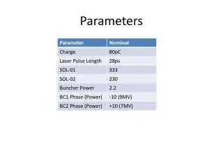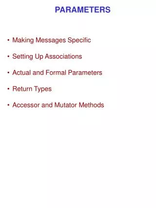
BASIC PARAMETERS
BASIC PARAMETERS. At ‘reference’ orbit (10 MeV?). COMBINING DIPOLE & QUAD FIELD. from experience, combining variable dipole and quadrupole field in the same magnet is difficult and expensive;

BASIC PARAMETERS
E N D
Presentation Transcript
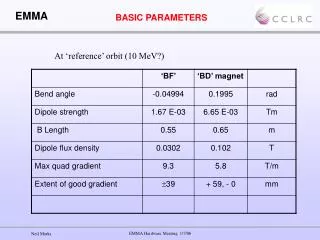
BASIC PARAMETERS At ‘reference’ orbit (10 MeV?) EMMA Hardware Meeting 1/7/06
COMBINING DIPOLE & QUAD FIELD • from experience, combining variable dipole and quadrupole field in the same magnet is difficult and expensive; • the series of ‘allowed’ harmonics in dipoles is n = 1, 3, 5, etc; ie dipoles are quadrupoles are ‘chalk and cheese’; • the parameters given above show that the EMMA magnets are substantially quadrupole magnets with low dipole components; SOLUTION: • build the EMMA magnets as pure quadrupoles; • position them off-centre to provide the dipole component; • when the ratio dipole/quadrupole needs to be varied, adjust the quad field and move the magnets radially to retain to correct dipole field. EMMA Hardware Meeting 1/7/06
MOVING MAGNETS DURING OPERATION IS NOT NEW! • In HERA (DESY), e- spin transfer into the longitudinal plane requires a horizontal and vertical bump to be applied after vertical polarisation has been achieved – • horizontal is applied first; • then the vertical bump is applied and magnet positions changed to keep beam inside the vacuum vessel. With thanks to Prof. Des Barber, DESY and U. of Liverpool. – see http://www.lancs.ac.uk/cockcroft-institute/education/Barber_spin_June06.ppt EMMA Hardware Meeting 1/7/06
BEFORE AND AFTER Before vertical bump is applied. After vertical bump is applied. With thanks to Prof. Des Barber, DESY and U. of Liverpool. – see http://www.lancs.ac.uk/cockcroft-institute/education/Barber_spin_June06.ppt EMMA Hardware Meeting 1/7/06
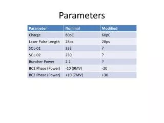
RESULTING MAGNET PARAMETERS EMMA Hardware Meeting 1/7/06
‘BF’ MAGNET FEA GEOMETRY One eighth cross section used for 2D f.e.a of BF magnet. EMMA Hardware Meeting 1/7/06
‘BF’ GRADIENT QUALITY (LINEAR STEEL) Expressed as: D(dBy/dx (x,0))/By/dx (0,0); Gradient: 10.1 T./m at J = 3.2 A/mm2; Gradient quality: + 0.25% at x = 34 mm; -0.35% at x = 39 mm; Max induction in pole root: 1.24 T. EMMA Hardware Meeting 1/7/06
‘BF’ GRADIENT QUALITY (NON-LINEAR STEEL) Identical quality to linear steel case. Gradient: 9.96 T; Hence, amplitude linearity: 98.6 %. EMMA Hardware Meeting 1/7/06
RESULTING ‘BF’DESIGN EMMA Hardware Meeting 1/7/06
‘BD’ MAGNET FEA GEOMETRY One eighth cross section used for 2D f.e.a of BD magnet; half-magnet geometry and mirror plate ignored (for the moment). EMMA Hardware Meeting 1/7/06
‘BD’ GRADIENT QUALITY (LINEAR STEEL) Expressed as: D(dBy/dx (x,0))/By/dx (0,0); Gradient: 6.19 T/m at J = 3.2 A/mm2; Gradient quality: + 0.04% at x = 45 mm; -0.28% at x = 59 mm; Max induction in pole root: < 1.0 T. EMMA Hardware Meeting 1/7/06
HALF ‘BD’ MAGNET WITH MIRROR PLATE EMMA Hardware Meeting 1/7/06
HALF ‘BD’ GRADIENT QUALITY (LINEAR STEEL) on y = 0 axis Expressed as: D(By/dx (x,0))/By/dx (0,0);between x = 5 and x = 60; (steel at x = 0 gives singularity in dBy/dx); Gradient quality: + 0.1% at x = 55 mm; - 0.25% at x = 59 mm. EMMA Hardware Meeting 1/7/06
HALF ‘BD’ GRADIENT QUALITY (LINEAR STEEL) on x = 0 axis Expressed as: D(Bx/dy (0,y))/Bx/dy (0,0); between y = 0 and y = 30; Gradient quality: + 0.03% at y = 30 mm; EMMA Hardware Meeting 1/7/06
RESULTING ‘BD’ DESIGN EMMA Hardware Meeting 1/7/06
CELL LAYOUT GEOMETRY NOTE MAGNET PROXIMITY EMMA Hardware Meeting 1/7/06
INJECTION/EXTRACTION PATH Note injection line cutting through mirror plate on median plane EMMA Hardware Meeting 1/7/06