Download
1 / 66
660 likes | 883 Vues
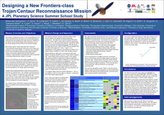
mission and ISD overview 6 October 2003. Steve Peters stevep@jpl.nasa.gov. contents. science rover operational paradigms vehicle baseline MSL surface GNC rover FSW functionality baseline project schedules ISD. science. rover-based science. location reconnaissance and remote science

E N D
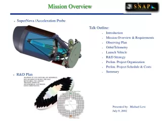
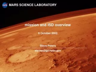
mission and ISD overview6 October 2003 Steve Peters stevep@jpl.nasa.gov
contents science rover operational paradigms vehicle baseline MSL surface GNC rover FSW functionality baseline project schedules ISD
rover-based science location reconnaissance and remote science look around, decide where to go characterize surface, decide which materials to investigate in situ target approach and contact science see, smell ... up close with hand lens characterize petrology, minerology, and chemistry of rocks and soils decide which materials to sample for analytical laboratory instruments sample acquisition and laboratory science return to lab and perform detailed analyses measure carbon, organics, and isotopes go to next location identified in data taken from orbit, and repeat all science decisions made by scientists on the groundno science autonomy source: M. Golombek
key aspects of MSL baseline large rover delivered by sky crane with no EDL hazard avoidance mobility system is landing gear, tolerant of hazards within landing ellipse hazards to mobility are sparce -- 130 m mean free path science scenario mission 1 Martian year (687 days = 670 sols) at each of 3 to 4 locations 3 sols location reconnaissance approach and take measurements of 19 to 25 targets at each of 28 to 74 targets 1 week to 10 days making contact measurements, acquiring samples, processing samples, and making laboratory measurements ground science in the loop at each step travel ~250 m between locations 5 sols @ 50 m/sol, planned on ground using stereo images total mission traverse from 3 to 6 km
rover algorithms in science scenario location reconnaissance no special autonomy throughput limited by downlink capacity target approach potential for autonomy to reduce sols consumed sample acquisition and processing no special autonomy performance driven by mechanism design and control algorithms throughput limited by ground loops for science decisions traverse potential for autonomy to reduce sols consumed traverse science low probability, high payoff potential for unanticipated scientific find meaningful only for long traverses passing features before seen by ground path into project is science AO proposal, funded by science, not project
potential benefits of onboard autonomy measures sols saved for science multipliers actions at each location (3 to 4) actions at each target (28 to 74) actions at each sol (670)
rover traverse -- sensory envelopes 1 2 what rover sees in 3D 3 what can be seen in orbital images, etc what rover sees in 2D to the horizon graphic assist: D. Eisenman
traverse MER 1 2 3 shading indicates primary responsibility for operational safety
rover instrument placement -- sensory envelopes what the rover sees in 3D at manipulator resolution within the manipulator workspace 1 2 3 what the rover sees in 3D at mobility resolution what rover sees in 2D to the horizon
instrument placement MER 1 2 3 shading indicates primary responsibility for operational safety
tuning validation • validation of specific terrain types • enables tuning scope of validation • operations people must understand terrains that have been validated • can revert to level-1 operations when entering unvalidated terrains • is not useful until terrain type is thoroughly validated • operations-time validation vs development-time validation • operations validation assures a particular instance of activity will work • development validation assures classes of activity will work • development validation during operations • entering unvalidated terrain acquires knowledge of the new terrain • models of new terrain is built and then used for validating new terrain • newly validated terrain is added to validated set
vehicle baseline (from surface system overview)
General Configuration Information • Mass Allocation: approx 900 kg • Wheelbase: 2.73 m • Wheel Size: 0.70 m • Track Width: 2.35 m • Maximum Obstacle Height: 0.75 m rock • Ground Pressure: 4.2 kPa (0.6 psi) • Top Deck Height: 1.5 m above ground • Mast Height: 4.0 m above ground • 2 Sample Acquisition Arms: 5 dof primary, 5 dof secondary • One Sol Range: 20 m - 100 m (50 m Nominal) • GNC Sensors: MER Cameras, LN-200, Sun Sensor • Effective Stereo Range (Navcams): approx 50 m • RPS Power: 220 W continuous (2 RPSs) • Thermal Control: Pumped RPS waste heat / heaters • DTE Link Performance: ~ 50 Mbit/sol • UHF Link Performance: 50-2000 Mbit/sol (link dependent) • Operational Lifetime: 687 Days/670 sols (baseline)
OpNav Cam Star Tracker Sun Sensor Surface Abrader MC Corer MC Scoop SA-SPAH functions MC MC Primary Arm MC Thermal Control/ Heat Rejection Pump assy. Secondary Arm MC Pump assy. Surface Ops Radiator Cruise Ops Radiator Heat Exchanger Cruise EDL Rover Patch Antenna Patch Antenna Telecom HGA LGA GNC Heritage High Partial New development PATR Antenna UHF Radio UHF Radio pol Antenna (UHF) Descent Imager Sun Sensor 2 Nav Cams 4 Haz Cams Patch UHF Ant. (EDL) As upscope PATR Electronics MIMU Flash for Night Ops X-Band SDST & Amplifier MIMU LN200 X-Band SDST & SSPA Amplifier LN200 HGA LGA (X-band) Mobility Sensors ? commanding 1553 bus U/L D/L data Power Electronics To Rover Loads** Power Electronics NV Memory FPGA SIO GIF ULDL DTCI NIC NV Memory FPGA SIO GIF ULDL DTCI NIC Compute Element pyros CEDL Controller NIC CEDL Controller NIC I2C bus Prop Avionics Temp sensor data To Cruise Loads* MSS to MSS Solar Array Temp sensor data Payload Mechanisms Payload (Heritage TBD) To EDL Loads* Remote Sensing SASPAH (Heritage TBD) pyros Cruise RTG Radiator HRS-1A,B Contact Instruments Pump assy HRS-2 Prop Thermal Battery Analytical Laboratory Instruments Propulsion Heat Exchanger Other Instruments PR Camera To RTG controller P/L Electronics Remote Sensing Mast MC Shunt Regulator Battery 1 Engineering Mechanisms Mobility MC RTG RTG RTG RTG Deployment Mech. MC Battery 2 HGA Gimbal MC 6/4/03
Heritage High Partial New development 2 independent fluid loops, each with one pump assy. Each loop goes to the avionics, base of RSM and arms, base of HGA, and the radiators ( ). One loop also goes to Mobility( ). Notes/Key • Telecom Cabling (Coax and W/G) • 1553 Bus (redundant) point-to-point connections • 1553 Bus (redundant) bus and connections to bus • I2C Bus (redundant) • Power line • PATR Data/Power I/F • Motor Control (Distributed) • Heater • Telecom Switch • Fluid Loop (HRS-1) • Temp Sensor Data • Upscope item • TBD Item Cruise EDL Avionics GNC Telecom MC Thermal Control/ Heat Rejection Mechanisms Payload Notes: *Power loads include pyros and telecom switches ()Telecom point-to-point interface with the compute element includes 1553, RS-422 and LVDS communication paths **Rover loads include heaters, thermal pumps, avionics, sensors, radios/transmitters, payload, etc -> Propulsion VME bus??? Grey Box w/dashed line Box w/dashed line
Hazcam FOV Hazcams define SA-SPAH work area There is a stereo pair of hazcams on the front and rear of the rover. Each camera has a FOV of 127 deg x 127 deg.
robotics and surface GNC • robotics functionality distributed across two teams • surface GNC (Ed Wong, Jim Alexander, et al.) • vehicle motion • positioning and pointing of remote and contact science instruments and GNC sensors • manipulation task (Paul Backes, et al.) • sample acquisition, handling, and processing • research-to-flight path for algorithms is through these teams
current surface system baseline • MER capabilities • stereo vision range sensing from MER (Maimone) • GESTALT hazard detection from MER (Maimone) • GESTALT hazard avoidance is upscope likely to be included • arm hazard detection from MER (Leger) • includes both environment and self-collision detection • project specified • position estimation from project GNC team • likely to include 6-DOF EKF estimation • driven by availability of IMU, support of night operations, etc. • manipulation from project manipulation task
current surface system upscopes • higher priority • GESTALT hazard avoidance from MER (Maimone) • already included with GESTALT hazard detection • visual odometry (Chang) • included in MER software • target tracking • reduction of target approach sols for all targets • lower priority • handoff target from mast to body cameras • amount and frequency of benefit dependent upon targets selected • arm hazard avoidance • benefit only for reachable targets in cluttered environments • reposition vehicle for manipulability • benefit dependent upon accuracy of approach and arm workspace • simple crabbing may suffice in most cases when useful
robotics algorithm prioritization process • meetings held to advise project on algorithm need and payoff • types of algorithms prioritized, alternative algorithms not prioritized • mission criticality • high = can't do mission without • medium = noticeable performance benefit to mission • low = low performance benefit or not applicable to mission • urgency for technology work • high = needs immediate work to be ready by PDR • medium = needs technology work prior to PDR • low = can be done within project development process • participants from MTP, MER and Sojourner, MSL, and 348 • new technology providers explicitly not requested in this forum • priorization results in spreadsheet • <URL>
robotics algorithm prioritization highlights • high criticality • stereo vision ranging • mobility hazard detection • position estimation • arm hazard detection • sample acquisition and handling (several items) • medium criticality / high urgency • target tracking • contact vector selection • arm control for coring • medium criticality / medium urgency • arm hazard avoidance • not on nor added to the prioritization list • handoff of tracking target from mast to body cameras
notes on alternative algorithms • alternative algorithms not prioritized • mobility hazard detection and avoidance • GESTALT (MER/Maimone) • DriveMaps (FIDO/Aghazarian) • Sojourner (Sojourner/Wilcox) • target tracking • 2D/3D target tracking (Rocky8/Nesnas) • homography-based target relative estimation (FIDO/Huntsberger) • 3D surface matching (K9/Deans) • mast to body camera target handoff (functionality not in prioritization list) • (Li) • (K9/Pederson) • single algorithm supporting function treated as default selection • algorithms supporting low criticality functions not listed here
rover FSW functionality baseline (from surface system FSW baseline description document)
Rover Software Design Descriptions (cont’d)FSW functions -- overview • robotic functions • traverse • target approach • instrument placement • sample acqusition • sample processing • position estimation • science operations • location reconnaissance • instrument observations • spacecraft operation • uplink/downlink • power management • thermal control • system operation • sequence execution • constraint monitoring • fault response
Rover Software Design Descriptions (cont’d)FSW functions -- traverse • initial conditions: • path to goal planned on the ground and uplinked • repeat until goal is reached: • take stereo image with body-mounted stereo camera pair • compute new "after" features and update position since last drive (visual odometry) • build range map from stereo images (stereo vision processing) • derive/update traversability/obstacle map • detect obstacles to step of motion • choose step of motion (~1/2 vehicle length) toward goal avoiding obstacles (GESTALT) • drive step • periodic while driving: • position estimation integrating IMU, wheel odometry, sun sensor, visual odometry (EKF) italics indicates upscope
Rover Software Design Descriptions (cont’d)FSW functions -- location reconnaissance • commanded/sequenced operations as appropriate: • point mast (science instruments and engineering cameras) • take remote science data • take engineering camera stereo images
Rover Software Design Descriptions (cont’d)FSW functions -- target approach • initial conditions: • path to goal for vehicle motion planned on the ground and uplinked • contact target approach vector estimated on ground and uplinked • repeat until vehicle motion goal is reached: • point mast stereo camera pair at contact target • compute new "after" feature set and update position relative to contact target since last drive (target tracking) • take stereo image pair with body-mounted stereo camera pair • build range map from stereo images (stereo vision processing) • derive/update traversability/obstacle map • detect obstacles to step of motion • choose step of motion (~1/2 vehicle length) toward goal avoiding obstacles (GESTALT) • drive step • periodic during driving: • position estimation integrating IMU, wheel odometry, sun sensor (EKF) italics indicates upscope
Rover Software Design Descriptions (cont’d)FSW functions -- deployment on target • procedure: • "handoff' of target from mast to body cameras • take stereo image pair with body-mounted stereo camera pair • build range map from stereo images (stereo vision processing) • derive 3D map of manipulator workspace map from range map and vehicle kinematics • plan collision-free manipulator trajectory • determine if arm can be safely unstowed and moved to target approach vector (fail operation if not safe) • reposition vehicle to enable contact operation and try again • unstow arm and move to target approach vector • move along approach vector until contact is sensed italics indicates upscope
Rover Software Design Descriptions (cont’d)FSW functions -- target contact operations • commanded/sequenced operations as appropriate: • take contact science instrument measurement • abrade rock surface • swap out corer bits • acquire mini-core of rock • acquire soil sample with scoop • deliver sample to sample handling and processing mechanism • crush sample • deliver sample to onboard analytic laboratory instrument • take analytic laboratory instrument measurement • notes: • here it is assumed that robustness is designed into mechanisms, reducing complexity of mechanism control software for the above operations -- research task is in progress italics indicates upscope
Rover Software Design Descriptions (cont’d)FSW functions -- spacecraft operation • uplink/downlink operations: • for DTE communications, point HGA to and track Earth within 0.5 deg • for UHF relay communications, wait for relay satellite to be in view • for X-band relay communications, point HGA at satellite and track • CFTP uplink and downlink communication via DTE and relay • receive uplink • merge uplinked goal net into executing schedule • perform uplinked flight state variable proxy updates • prepare data for downlink • downlink as-executed goal nets and event logs • delete lower-priority engineering data to meet data storage constraints • compress data as allowed to meet data storage constraints italics indicates upscope
Rover Software Design Descriptions (cont’d)FSW functions -- spacecraft operation • power management: • load sensing • power switching • charge batteries • thermal control: • temperature sensing • heater switching
Rover Software Design Descriptions (cont’d)FSW functions -- system operation • sequence execution: • constraint-driven estimation and control • goal net execution • monitoring goal net execution • constraint monitoring: • monitoring health states • monitoring resource usage within planned margins • monitoring operational constraints (flight rules) • fault response: • detect constraint violation • interrupt goal net execution • prepare fault response goal net • merge fault response goal net with current state • transfer execution to updated goal net
Rover Software Design Descriptions (cont’d)FSW functions -- functionality not managed by rover FSW • control of rover-mounted EDL equipment: • descent radar • EDL telecom antenna • some separation mechanisms • passive or automatic hardware functions: • heat loop pump operation
samplehandling science articulation vision mobility thermal power telecom deployments mast, contact, and laboratory instruments encoders potentiometers motors sample sensors abrader mini-corer scoop encoders poltentiometers strain gauges motors cameras flash encoders potentiometers motors IMUs sun sensors temperature sensors heaters battery chargesensorsswitches current sensors HGA LGA UHF (Electra) SDSTs separation nuts actuators launch locks electrical disconnects Rover Software Design Descriptions (cont’d)FSW subsystems infrastructure subsystem mission planningand execution data managementand data transport adaptation subsystem nominal operations health monitoring and fault protection subsystem hardware interfaces goal nets states delegation measurements GNC italics indicates upscope
each adaptation subsystem in an MDS deployment infrastructure subsystem elaboration can generate goals on external subsystems adaptation subsystem elaborators nominal operations health monitoring and fault protection subsystem hardware interfaces goal nets goals state information is available to the rest of the system (including downlink to Earth) some goals require elaboration while others are achieved directly state variables states delegation multiple states may be required for estimation (along with measurements) estimators controllers measurements hardware adapters measurements are available to multiple estimators (can be used to estimate different states, even in different subsystems) coordinated control accomplished by direct communication between controllers, can involve coordination across subsytems device 1 device 2 device 3 ...
FBO rel 10/03 Inst CDR 12/06 Inst PDR 11/05 Inst sel 10/04 AO rel 3/04 6/09 3/07 5/06 3/05 4/11 9/12 10/10 10/09 project schedule13 August 203 02 03 04 05 06 07 08 09 10 11 12 FY 02 03 04 05 06 07 08 09 10 11 12 CY Pre A A B E C D Phase (18) (17) (14) (23) (35) Duration 10/21-22/03 2/08 Ship MCR PMSR PDR CDR ARR Mars Lndg Solar EOM Nuclear EOM Event Launch 4/08 ATLO Start Inst del 6/1/08 Proposals due 6/04
ATLO Start 2/2/08 PSRR 6/1/09 ARR 12/1/07 Launch CY2007 CY2008 CY2009 ATLO schedule27 October 2003 Payload Deliveries 2/08-3/08 Del Int FT M (2) Payload Module 6/30/08 M (2) ARR - ATLO Readiness Review Del - Delivery EEIS - End-to-End Information System Env - Environmental Test Int - Integration FT - Functional Test M - Project Margin (duration) MDVT - Mission Design Verification Test ORT - Operational Readiness Test PSRR -Pre-Ship Readiness Review S - Stack, inc MMRTG integration rehearsal M (0.5) Integration FT Thm FT Rover M (0.5) FT (2.0) S(1.5) Integrated System Test 9/15/08 Env (2.5) M (2.0) 1/2/09 4/1/09 Int + FT M (1) Int EDL System 6/9/09 7/1/08 Int Cruise Stage Launch window 7/29/08 10/4-11/4 MOS Test windows: MDVT/EEIS/ORTs Post-Delievry Margin = 4 months Duration = 18 months
ISD schedule • R-1 (3/29/02) • Basic mobility on FIDO simulation: • 6 wheel drive and turn in place • 3-D ROAMS visualization • Core frameworks: • State, goal, data management and transport, state query, sim adapters and devices, etc… • Core infrastructure: • component architecture, initialization, test harness, etc… • R-3 (11/15/02) • Rocky 7 Stereo vision processing • Hazcam images and control • Disparity / terrain maps • GESTALT hazard detection • Map and image data products • State triggered goals • Goal failures w/ basic unconstrained prudent behavior • Constraint sets • Ops scenario descriptions • R-2 (8/15/02) • Basic mobility on Rocky 7 hardware: • 6 wheel drive and turn in place • PowerPC 750 and VxWorks • Hardware adapters: • Device drivers • Command processing • Measurement processing • Basic mobility on Rocky 7 simulation • Simulated FIDO basic mobility on VxWorks • R-6 (8/15/03) MCR • Rocky 7 adaptation • Extended Kalman filter estimation of position and heading • Gyro device driver • Real time execution • Rocky 7 ROAMS basic mobility (wheel motors and encoders) • WITS uplink • 2nd generationstate database tool • Multi-threaded data transport • R-5 (5/15/03) • Rocky 7 simulated gyro adaptation • Testability • Real-time telemetry • Goal directed delegation • Power resource and margin states • State prediction based on intent • Data states and goals • Goal directed real-time and selective downlink • WITS downlink • VxWorks CPU use snapshots • R-4 (2/15/03) • Rocky 7 GESTALT hazard avoidance • Allocation and delegation goals • Uplink data products & transport • Operability • Multi-threaded execution framework • Solaris metrics for memory and execution time • Stress Test (# of goals, duration) • Drive arcs with faults Some new core capability needed External Release Internal Release
ISD schedule • Release 7 (internal) -- 11/15/03 • Process and product performance • Rocky 7, Solaris, and Linux • Release 8 -- 2/15/04 • Rocky 8 basic mobility (hardware and sim) • Release 9 (internal) -- 5/15/04 • Rocky 8 GESTALT hazard detection and avoidance (hardware and sim) • Release 10 -- 8/15/04 • Rocky 8 basic manipulator control (hardware and sim) • Release 11 (internal) -- 11/15/04 • Rocky 8 instrument placement (hardware and sim) • Release 12 -- 2/15/05 • Rocky 8 final approach (mobility) (hardware and sim) • Release 13 (internal) -- 5/15/05 • ISD functionality completed (hardware and sim) • Exercise integrated final approach & instrument placement. • Release 14 -- 8/15/05 • Integrated software demo on Rocky 8 (hardware and sim) • Metrics collection and performance tuning completed • Release 7 through 14 planning is incorporating capabilities needed to meet ISD requirements on Rocky 8 • See Sandy’s presentation on ISD requirements. • Requirement review and analysis will develop increments and dependencies for new framework, adaptation, technology infusion, infrastructure, performance capabilities.
ISD (integrated software demonstration)
questions to answer about MDS • can MDS work as an embedded system? • shown in August 2002 when MDS moved in 4 months from Solaris workstation simulation of FIDO mobility to functional on-board implementation of Rocky 7 mobility • can MDS implement robotics algorithms of required complexity? • shown in May 2003 with implementation of MER GESTALT • does MDS provide required fault response support? • does MDS scale to real mission complexity? • can MDS support coodinated control closing the loop through the environment? • do we know how to operate an MDS-based system? • can an MDS implementation be validated?
demonstrations to answer questions • "integrated software demo" on Rocky8 to address robotics and operability questions • summary follows • simulation-based demos to address performance and scalability questions • need to be defined
onboard robotics algorithms in the ISD • stereo vision (MER/Maimone) • basic mobility (vehicle-dependent) • GESTALT mobility hazard detection and avoidance (MER/Maimone) • basic 5-DOF arm control and contact sensing (MSL/Backes) • arm hazard detection (MER/Leger)