Download
1 / 24
240 likes | 319 Vues
This document details the outcomes of the 2007 BLM hardware tests in LSS5 and a maintenance request by Daniel Kramer for the BLM team in 2008. It discusses installations, system comparisons, space charge effects, cable crosstalk studies, and resulting actions for the LHC installation. The text provides insights and recommendations related to collimation areas and beam dump on closed jaws. It also includes information on current limitations, signal processing, and system configurations for optimal performance.

E N D
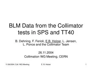
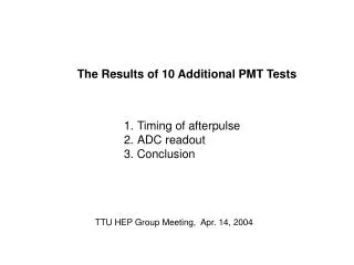
Results of the 2007 BLM hardware tests in LSS5 ..And a coast MD request for the 2008 Daniel Kramer for the BLM team
Standard BLMI ARC installation Small low pass filter in the CFC input stage HV ground cut here BLMI HV Power Supply CFC is always close to the quadrupole Up to 8 BLMs connected in parallel Collimation WG D.Kramer
BLMI installation for collimation areas 8 chambers in 1 NG18 cable (up to 700m) HV capacitor removed 6 HV capacitors in parallel 150k for current limitation 280pF = chamber’s capacity Collimation WG D.Kramer
SPS LSS5 Installation – System A • study space charge effects with large doses • Compare directly BLMI with SEM AIM: • large capacitor directly on the HV side • Cf capacitor directly on the signal side • 150kOhm after Cf -> large time constant Collimation WG D.Kramer
SPS LSS5 Installation – System B • study cable crosstalks with different filters • verify the peak current limitation by the 150k resistor AIM: • Cf capacitor directly on the signal side • 150kOhm on HV side -> current limitation Collimation WG D.Kramer
BLM installationin LSS5 of SPS System A System B Collimation WG D.Kramer
Beam dump on Closed JawsSEM to BLMI comparison 1.3 1013p+ Black line – signal not clipped 5*τ_filter = 350ms Collimation WG D.Kramer
BLMI Space charge effect estimation (“signal saturation”) Collimation WG D.Kramer
BLMI Space charge effect estimation (“signal saturation”) • SEM expected to be “saturation free” • BLMI’s expected deposited dose to be scaled by SEM/BLMI ratio from FLUKA (50% errorbarx) Collimation WG D.Kramer
150kOhm resistor limitation(between HV capacitor & IC) • Limits the peak current on the chamber input to 1500 / 150k = 10mA • Fast loss has only the Chamber charge available 280pF * 1500V = 0.4 uC • Corresponds to ~ 7 mGy total loss • Corresponds to ~ 180 Gy/s (PM limit = 22 Gy/s..) • Slows down the signal collection • DC current limited to 1500 / 1M = 1.5 mA • Corresponds to ~ 26 Gy/s (total in max 8 chambers) Collimation WG D.Kramer
Cable crosstalks studySystem A • Ch 8 unconnected • Ch 2 saturated • Xtalk should be proportional to the signal derivation • Signal peak ratio 4.3e-3 (47dB) • Integral ratio 1.4e-4 (77dB) Collimation WG D.Kramer
Cable crosstalks studySystem B • Ch 6..8 unconnected • Xtalk clearly depends on the derivation • Signal peak ratio 5e-2 (26dB) (worst case) • Integral ratio 4.4e-3 (47dB) • No fundamental difference between A and B Collimation WG D.Kramer
Resulting actions for the LHC installation • HV cables separated between SEM and BLMI • Signal cables (NG18) not shared by SEM and BLMI • CFC cards not shared either • For collimation areas • capacitors removed from the chambers • 150kOhm resistance to limit the i/o BLMI current Collimation WG D.Kramer
System A 1.3e13 p+ dumped on collimator,Left Jaw at -5 mm, Right Jaw out Collimation WG D.Kramer
System A 1.3e13 p+ injection plateau,Left Jaw at 10mm, Right Jaw out, Dump @ 1.2s Collimation WG D.Kramer
FFT of the previous plot (red channel from 200 to 1200ms)Different scales presented The 3-phase power supply lines similar to the coasting case. 600Hz should be caused by the 12-pole converter of the rectifier
Jaw not closed: comparison of system A and B Sys A Sys B Collimation WG D.Kramer
MD request for 2008 • 2007 halo oscillations estimated to ~1.8 um • Aim is to verify the beam halo position oscillations • by using both horizontal jaws (LHC collimator) • By using vertical jaws of the SPS collimator • Is the beam center moving? (fast BPMs) • Need • coasting beam 270 GeV • Up to 12 bunches • LHC Collimator control • SPS Collimator control 2006 data CWG 19/3/07 Collimation WG D.Kramer
W37 Coasting beam 270GeV 200um Left jaw move, no signal filters Collimation WG D.Kramer
W37 Coasting beam 270GeV 200um Left jaw move, no signal filters Collimation WG D.Kramer
Spare plots 2 H4 Calibration of the SEM (to be presented later)