Download
1 / 42
440 likes | 640 Vues
Explore principles of measurement and sensor types in biomedical electronics, including resistive, capacitive, inductive, and piezoelectric sensors. Understand transduction processes, active vs. passive sensors, and displacement measurement methods for medical applications.

E N D
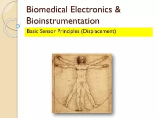
Biomedical Electronics & Bioinstrumentation Basic Sensor Principles (Displacement)
Contents • Principles of Measurement • Wheatstone Bridge • Resistive Sensors • Capacitive Sensors • Inductive Sensors • Piezoelectric Sensors
Principles of Measurement • Most medical instruments are electronic devices and so must have an electrical signal for an input. • When a biopotential must be acquired, some form of electrode is used between the patient and the instrument. • A sensor is used to convert some non-electrical parameter or stimulus, such as force, pressure, or temperature, to an analogous electrical signal proportional to the value of the original stimulus parameter.
Principles of Measurement • Dimensional changes are measurable via resistive, inductive, capacitive and piezoelectric effects. • Body temperature are measurable through use of thermistors and thermocouples. • Electromagnetic-radiation sensors include thermal and photon detectors.
Transduction • It is necessary to understand the linked concepts of transduction and tranducible property. • A transducible property is a characteristic of the physical event that is singularly able to represent that parameter and be transformed into an electrical signal by some device or process. • Transduction is the process of converting the transducible property into an electrical signal that can be input to an instrument.
Transduction • Example: CO2 absorbs EM wavelengths of 2.7, 4.3 and 14.7µm. Although water also absorbs 2.7µm radiation to a small degree, it is possible to make an IR sensor that will respond to either 4.3 or 14.7µm or all three wavelengths to measure CO2 content of a gas, such as air. End-tidal CO2 monitors, used in respiratory therapy, intensive care, and anesthesia, use IR sensors.
Active Vs Passive Sensors • An active sensor requires an external ac or dc electrical source to power the device. • Without an external excitation potential, there is no output from the sensor. • Example: Resistive strain gauge blood pressure sensor that requires a +7.5V dc-regulated power supply to operate.
Active Vs Passive Sensors • A passive sensor, on the other hand either provides its own energy or derives its energy from the phenomena being measured. • Example: The thermocouple, which is often used to measure temperature in research settings.
Displacement Measurement • Physicians and biomedical researchers interested in measuring the size, shape and position of the organs and tissues in the body. • Variations in these parameters are important in discriminating normal from abnormal function. • Displacement sensors can be used in direct and indirect measurement. • Direct measurement to determine the change in blood vessel diameter and the changes in volume and shape of the heart chambers. • Indirect measurement to quantify movements of liquids through the heart valves.
Displacement Measurement • Displacement-sensitive measurement methods: • Resistive • Inductive • Capacitive • Piezoelectric
Bridge Circuits • Do you remember the Wheatstone Bridge? • The bridge is suitable for measuring small change in resistance. • It is said the bridge is balanced when the ratio of R1/R2 is equal to R3/R4. • Prove the above relationship.
Bridge Circuits • Given V = 5V • Sketch the graph of Vb – Va against R1 if R2 = R3 = R4 = 1kΩ. Va Vb R1 R3 V R2 R4
Bridge Circuits • Resistive-type sensors may be connected in one or more arms of a bridge circuit. • An example of resistive-type sensor is the strain gauge. • Give me another example of a resistive-type sensor. • Varying resistance is detected either by: • Null-balance bridge circuit • Deflection-balance bridge circuit
Bridge Circuits • Null-balance bridge results when the resistance change of the sensor is balanced (zero-output) by a variable resistor in an adjacent arm of the bridge. • Deflection-balance method utilizes the amount of bridge unbalance to determine the change in sensor resistance. • Now, the question is do we really need bridge circuits? Why?
Bridge Circuits • Application In the mercury-in-rubber strain gauge plethysmography, four lead gauge are applied to the human calf. The bridge output provides information on venous-occlusion plethysmography as well as arterial pulse plethysmography.
Potentiometers • How do we relate this following circuit to a simple concept of potentiometer? • What varying element do we add in this circuit? • Write me the relevant equation. V RA RB
Potentiometers • 3 types: • Translational displacement • Single-turn rotational displacement • Multi-turn rotational displacement • Linear output from these devices (0.01% of full scale) as a function of displacement. • Resolution is a function of construction.
Potentiometers • Possible to construct continuous stepless conversion of low value resistance using straight piece of wire. • For greater resistance, the resistance wire is wounded on a mandrel or card.
Strain Gauge • What is elasticity? • Show me the relevant elastoplastic graph of a material. • Imagine a wire within its elastic limit. • What happens to its resistance when the diameter and length changes. • Provide me with a relevant equation for this situation.
Strain Gauge • Types of strain gauges: • Bonded • Unbonded • Explain the difference between these 2 types based on its terminology. • We must always bear in mind that the behavior of strain gauges are influenced by its gauge factor, G.
Strain Gauge • The gauge factor is given by: • Derive the above equation. • In practical existence, there are two types of strain gauges • Metal strain gauge • Semiconductor strain gauge
Strain Gauge • Observe the dimensional and piezoresistive effects. • What is the difference in these effects for the metal and semiconductor strain gauges? • Please note that strain gauges also have temperature coefficient of resistivity which differs between materials.
Capacitive Sensors • The capacitance between two parallel plates of area A separated by distance d: Where 𝜀0 : Dielectric constant of free space 𝜀r : Dielectric constant of the insulator
Capacitive Sensors • In principle it is possible to measure change in displacement by changing 3 parameters 𝜀r, A or d. • However, the most practical is by changing separation between the plates. • Sensitivity K of a capacitive sensor to change in plate separation ∆d is given by:
Capacitive Sensors • Application: • Compliant plastics of different dielectric constants can be placed between foil layers to form a capacitive mat to be placed on the bed. Patient movement creates charge, which is amplified and filtered to display respiratory movement from the lungs and ballistographic movements of the heart.
Capacitive Sensors • Application: • Sensor can also be fabricated from layers of mica insulators sandwiched between corrugated metal layers. Applied pressure flattens the corrugations and moves the metallic plates closer to each other, thus increasing the capacitance. The sensor measures the pressure between the foot and shoe.
Inductive Sensors • Inductance L measures displacement by varying any three of the coil parameters. • Each parameter can be changed by mechanical means. Where n : Number of turns of coil G : Geometric form factor µ : Effective permeability of medium
Inductive Sensors • Inductive-displacement sensors consist of: • Single coil • Reactive Wheatstone bridge • Linear voltage differential transformer • Inductive sensor has the advantage of not being affected by dielectric of its environment. • However, may be affected by external magnetic fields.
Inductive Sensors • Single coil devices are rarely used in modern equipment. Why does this happen? • The reactive Wheatstone bridge sensor is used for measurement of arterial and venous blood pressure. • The transduction occurs because of a change of position of the inductor’s core. • But this yields only position data unless the applied force operates against some other force such as spring.
Inductive Sensors • The amplitude is proportional to the magnitude of the applied pressure, while the phase indicates whether the pressure is positive (in compression) or negative (a vacuum). • Can anyone suggest the modification of the bridge that needs to be done to implement an inductive sensor into its the arms?
Inductive Sensors • LVDT composed of a primary coil and two secondary coils in series. • Coupling achieved by motion of high-permeability alloy core between them. • The secondary coils are connected in opposition to increase region of linearity. • The primary coil is sinusoidally excited, with frequencies between 60Hz to 20kHz.
Inductive Sensors • Alternating magnetic field induces nearly equal voltages in both the secondary coils. • Output VOut given by: • When a core is symmetrically placed, the two secondary voltages are equal and the output signal is zero. Where, V1: Voltage induced in the 1st secondary coil V2: Voltage induced in the 2nd secondary coil
Inductive Sensors • LVDT characteristics: • Linearity over a large range. • Phase change of 180° when core passes center position. • Saturations on the end. • Advantage: • Sensitivity of LVDT is much higher than the strain gauges.
Inductive Sensors • Disadvantages: • Requires more complex signal processing instrumentation. • Needs a phase-sensitive demodulator to determine direction of displacement. • Application of LVDT seen in measurement of pressure, displacement and force.
Piezoelectric Sensors • Piezoelectric materials generate electrical potential when mechanically strained. • Conversely an electrical potential can cause physical deformation of the material. • Used to measure physiological displacements. • Give an example application of piezoelectric sensor.
Piezoelectric Sensors • Principle of operation: • When an asymmetrical crystal lattice is distorted, a charge reorientation takes place, causing a relative displacement of negative and positive charges. • The displaced internal charges induce surface charges of opposite polarity on opposite sides of the crystal. • Surface charge determined by measuring voltage difference between electrodes.
Piezoelectric Sensors • Initially we assume infinite leakage resistance. • The total induced charge is directly proportional to the applied force, f with k as the piezoelectric constant. • Voltage change assumes the system acts like a parallel plate capacitor.
Piezoelectric Sensors • Typical values for k are 2.3pC/N for quartz and 140pC/N for barium titanate. • For sensor of 1cm2 area and 1mm thickness with an applied force due to 10g weight, the output voltage for quartz and barium titanate is 0.23mV and 14 mV respectively.
Piezoelectric Sensors • There are various modes of operation of piezoelectric sensors, depending on the material and the crystallographic orientation of the plate. • Thickness or longitudinal compression • Transversal compression • Thickness-shear action • Face-shear action.
Further Reading… • Webster, J.G. (1997). Medical Instrumentation: Application and Design. 3rd Ed., Wiley. • Chapter 2 • Carr, J.J. (2000). Introduction to Biomedical Equipment Technology. 4th Ed. Prentice Hall. • Chapter 6