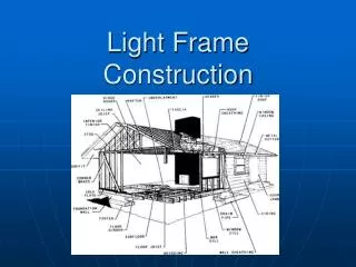
Light Frame Construction
Light Frame Construction. History. Light wood frame construction invented in 1830 in Chicago by George Washington Snow He recognized that closely spaced vertical members used to fill space in walls of heavy timber was strong enough to carry weights

Light Frame Construction
E N D
Presentation Transcript
History • Light wood frame construction invented in 1830 in Chicago by George Washington Snow • He recognized that closely spaced vertical members used to fill space in walls of heavy timber was strong enough to carry weights • Small boards and framing members became inexpensive due to new milling practices • Machine made nails became cheap compared to hand forge nails • Called balloon frame because it seem so thin
Balloon Frame • Joist – Floors • Studs – Walls • Rafters – sloping roofs • Disadvantages • Fire strips required • Studs are to long to be erect efficiently
Platform Frame • Floor • Wall – Load bearing • Floor • Wall – Load bearing • Attic/roof • Advantages • Short studs • Automatic fire stops • Convenient working surfaces • Disadvantages • Each platform constitutes of a thick layer of wood whose grain runs horizontally • Leads to vertical shrinkage –leads to distress in exterior or interior finish surfaces
Platform Frame Sheathing • Is the key component for platform framing • The end nails that connect the plates to the studs have little holding power against uplift of the roof by wind but the sheathing connects the frame into a single strong unit from foundation to roof. • The rectilinear geometry of the parallel framing members has no useful resistance to wracking by lateral forces such as wind, but rigid sheathing panels or diagonal sheathing boards brace the building effectively against a surface to which shingles boards and flooring are nailed for finished surfaces.
Foundation for light Frame Structures • Foundations for light framing originally made of stone or brink – are now made in most cases of site cast concrete, concrete block masonry or preservative treated wood • Concrete and masonry foundations are highly conductive of heat and usually must be insulated to meet code requirements concerning energy conservation. • Wood foundation is easily insulated in the same manner as the frame of the building it supports • Further advantages claimed for wood foundations are that they can be constructed in any weather by the same crew of carpenters that will frame the building and they allow for easy installation of electrical wiring plumbing and interior finish materials in the basement.
Planning the frame • Architectural floor plans serve to indicate the locations and dimensions of all walls, partitions and openings • Exterior elevations are drawings that show the outside faces of the building with vertical framing dimensions indicated as required. • Sections are also drawn that cut completely through the building showing the
Erecting the Frame • Notice the basic simplicity of the building process • A platform is built walls are assembled horizontally on the platform and tilted up into place and another platform or a roof is built on top of the walls • Work is accomplished without the use of ladders or scaffolding and temporary bracing is needed only to support the walls until the next level of framing is installed and sheathed.
Attaching the frame to the foundation • The sill preferably preservative treated or naturally decay resistant wood is bolted to the foundation as a base for the wood framing . • A single sill is all that is required by most codes but in better quality work the sill is often doubled for greater stiffness • The top of the foundation is usually somewhat uneven, so at low spots the sill must be shimmed with wood shingle wedges to be able to transfer loads from the frame to the foundation • A compressible fibrous sill sealer should be inserted between the sill and the foundation to reduce air infiltration through the gap. • The normal foundation bolts are sufficient to hold most buildings on their foundations, but tall frames in areas subject to high winds or earthquakes may require more elaborate attachments.
Floor Framing and Bridging • The standard joist spacing are 16 or 24 o.c., measuring from center tot center of the joists • Any of these spacing automatically provides a joist at every panel end • Sub flooring should be glued to the joists to prevent squeaking and increase floor stiffness • Plywood and OSB panels must be laid with the grain of their face layers perpendicular to the direction of the joists because these panels are considerably stiffer in this orientation • Sheathing and sub flooring panels are normally manufactured 1/8” • Bridging which is cross bracing or solid blocking between joist at midspan in a tradional feature of floor framing
Floor Framing and Bridging 2 • Its function is to hold the joists straight and to help them share concentrated loads • Although many building codes no longer require bridging, it should be used on better quality buildings because it makes a noticeable difference in the rigidity of a floor. • Where needs of joists butt into supporting headers as around stair openings and at changes of joist direction for projecting bays end nails and toe nails cannot carry the full weight of the joists and sheet metal joist hangers must be used. • Manufactured I joists and floor trusses are increasingly used in place of sawn joist because they can span farther between supports and they tend to be straighter.
Wall framing Sheathing and Bracing • Some building codes require blocking to be installed at the mid height of the studs in wall frames that are taller than 8 ft. The purpose of this blocking is to stop off the cavities between studs to restrict the spread of fire. • Headers over window and door openings must be sized in accordance with building code criteria. Typically, a header consists of two nominal 2 inch members standing on edge separated by a plywood spacer that serves to make the header as thick as the depth of the wall stud.
Roof Framing • Pitch is specified as a ratio of rise to run • Rise is the vertical dimension and run is the horizontal • In the united states pitch is usually given on the architects drawings as inches of rise per foot of run
Prefabricated framing Assemblies • Roof trusses and floor trusses find widespread use in platform frame buildings because of their speed of erection, economy of material usage and long span. • Most are light enough to be lifted and installed by two carpenters • Manufactured wall panels have been adopted more slowly than roof and floor trusses, except by large builders who mass market hundreds or thousands of homes pre year.