
SlideServe
Menu
Préférences
© SlideServe · v2026

Outline of MIPS Simulator project

casey avatar
14 diapositives · 394 Views · Aug 15, 2014

Outline of MIPS Simulator project. Write a simulator for the MIPS five-stage pipeline that does the following: Implements a subset of the instruction set (ADD,SUBI,OR, LW, SW, BEQ, BNE, J, SLT) Reads from a file an assembly language program
Outline of MIPS Simulator project - slide 1
01 / 14Outline of MIPS Simulator project
1 / 17

Télécharger la présentation

Outline of MIPS Simulator project
Une image / un lien ci-dessous est fourni (tel quel) pour télécharger la présentation

Politique de téléchargement : le contenu du site vous est fourni TEL QUEL pour votre information et votre usage personnel ; il ne peut être vendu, concédé sous licence ni partagé sur d’autres sites sans l’accord de son auteur.Le contenu vous est fourni TEL QUEL, pour votre information et votre usage personnel uniquement. Téléchargez la présentation en cliquant sur ce lien. Lors du téléchargement, si vous ne parvenez pas à télécharger une présentation, l’éditeur a peut-être supprimé le fichier de son serveur.Pendant le téléchargement, si vous ne parvenez pas à obtenir une présentation, le fichier a peut-être été supprimé par l’éditeur.

F I N

Plus de contenu associé

Transcription de la présentation
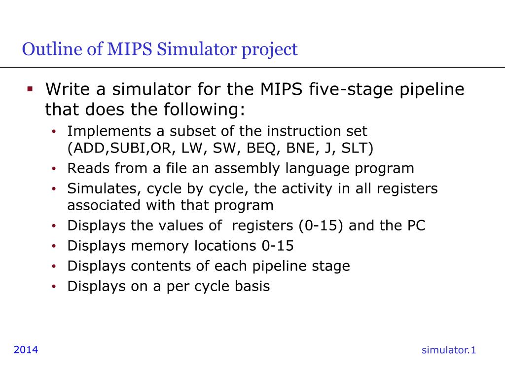
  1. Outline of MIPS Simulator project • Write a simulator for the MIPS five-stage pipeline that does the following: • Implements a subset of the instruction set (ADD,SUBI,OR, LW, SW, BEQ, BNE, J, SLT) • Reads from a file an assembly language program • Simulates, cycle by cycle, the activity in all registers associated with that program • Displays the values of registers (0-15) and the PC • Displays memory locations 0-15 • Displays contents of each pipeline stage • Displays on a per cycle basis

  2. Sample GUI – timing diagram – registers – memory – pipe stages

  3. Type of Simulator: Architecture Simulator • Time-Driven Simulator: Has a central clock and moves from one clock cycle to the next, simulating all the activity of interest in that clock cycle.

  4. Five-Stage Pipeline • IF Stage: Fetches instructions • If a conditional branch is encountered, use the predict not taken scheme explained in class • The IF stage places fetched instructions in an instruction queue, to be consumed by the ID stage. • Assume the PC has its own dedicated adder to increment the byte address by 4 (or word address by 1). • ID Stage: Decodes the instructions in the instruction queue, one by one. • Immediate operands are sign-extended to 32 bits • Makes operands available to the EX stage • Generates control signals

  5. register forwarding, we need the new value for instruction 0 within the ALU phase of instruction 1.

  6. Five-Stage Pipeline (contd.) • EX Stage: • Executes arithmetic/logical instructions • BEQ instructions are resolved in this stage • Check data dependencies and implement forwarding • MEM Stage: • Carries out access to the data memory • WB Stage: • Writes back into the register file (if necessary)

  7. Parsing Instructions • The assembly language program must be read by the simulator • You can use a case statement associated with each possible instruction, which tells the simulator what to do with that instruction. • When an instruction reaches the ID stage, controls governing the rest of its activity will be generated.

  8. A Straightforward Approach • Mimic within the simulator what happens in the MIPS pipeline • Generate the control signals associated with each instruction in the ID stage • Pass these signals along, stage by stage, along with the instruction. • check for data hazards • Every clock, mimic what is supposed to happen in each of the five stages and collect statistics on which stages are doing anything useful

  9. Maintain Data Memory State • Keep track of the contents of the data memory • Assume the data memory size is 16 words • Assume the instruction memory size is 16 words • Data and instruction address spaces are separate

  10. Instruction Memory & Register File • The program starts at location 0 of the instruction memory • The PC will point to this location at the beginning of the simulation • Each memory access takes 1 cycle • You can limit implementation to use registers 0-15

  11. Simplifications • To make it easier for you to read in the assembly language program: • The assembly language use commas to separate operands; • No register names will be used: register numbers only. • Example: add 3 2 1 means add register 1 contents to those of register 2 and put the result in register 3. • Don’t use labels in your program: instead the beq instruction will identify its target by an offset. • Example: beq 4 5 -2 means that if the contents of registers 4 and 5 are identical, we branch to the instruction immediately preceding beq.

  12. Reading the Assembly Language Program • C provides a number of ways in which to read input. For example, fscanf(fp, “%s %d %d %d”, opcode, &field2, &field3, &field4); where fp is a file pointer, opcode is a character array, and field2, field3, and field4 are integers

  13. Parsing the Assembly Language Program • Some useful library functions (remember to #include <string.h>): • strcpy: Copies one string into another • strcmp: Compares two strings. Note that this will give you an output of 0 if the two strings match.

  14. Simulator Output • The simulator must operate in single-step mode • Output consists of • Contents of each of the first 16 registers $1 to $15 and that of the PC (in decimal) • Output of data memory (0-15) • The number of clock cycles that have elapsed • Contents of each stage IF, ID, EX, MEM, WB.