Development of a Wind Speed Data Logger for Renewable Energy Assessment
This project outlines the design and implementation of a wind speed data logger aimed at supporting renewable energy initiatives. The data logger will facilitate the assessment of potential residential wind generator installations by measuring average wind speeds at various sites in Indiana and Ohio. The system includes an anemometer, a data logger, and communication modules designed for cost-efficient and user-friendly operation, providing valuable data crucial for determining the return on investment for wind energy projects.


Development of a Wind Speed Data Logger for Renewable Energy Assessment
E N D
Presentation Transcript
Wind Speed Data LoggerChuck Craft, Chuck Craft., Jr., Professor Paul I-Hai LinDate: Sept. 20-23, 2012
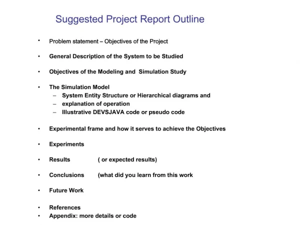
Project Outline • Introduction • Problem Statement/Solution • System design • Hardware design • Software design • Integration • testing • Conclusion
Introduction • Wind Speed Data Logger project supports the renewable energy market • Large wind generator installations are located in Indiana and Ohio • Average wind speed site surveys predict wind generator return on investment • Test towers erected at potential wind generator sites to gauge average wind conditions • Residential wind generator installations have the potential to be profitable • Wind speed data logger project provides affordable tool for residential wind survey
Problem Statement/Solution • Viable wind energy exists in our area • Wind generator output power is dependent on • Structures • Site topology • Industrial wind survey equipment is expensive • Wind speed data logger provides affordable easy to use tool for residential wind survey
System Design • Anemometer • End point controller • Access point controller • Data logger controller
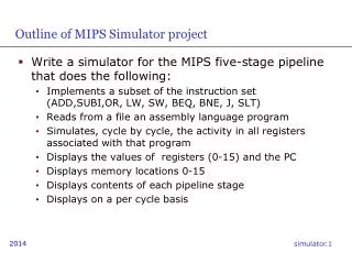
System Requirements • The prototype shall measure wind speed • The prototype shall transfer wind speed information from sensor to data logging device • The prototype shall store wind speed information in non-volatile memory • The prototype shall accept operator input and display wind speed • The prototype shall be capable of measuring wind speeds between 5 and 50 miles per hour
System requirements (Cont.) • The anemometer output shall be electrically conditioned to logic levels • The pulse stream from the anemometer shall be converted to one pulse per second at a wind velocity of 2.5 miles per hour • The anemometer shall be designed for pole mounting • Outdoor based electronics shall be mounted in an enclosure • The electronics shall operate off of standard household AC power • Information shall be transferred from the anemometer to a processing element via a data link, either cabled or RF
Hardware Design • Commercial Off The Shelf (COTS)building blocks • Vortex anemometer • Texas Instruments eZ430 evaluation module • Atmel AVR32 EVK1100 development module • RS232 adaptor
Hardware Design (Cont.)Vortex Anemometer Specifications • Sensor type • 3-Cup rotor reed switch/magnet provides 1 pulse per rotation • Output • 1 pulse per rotation at 2.5 mph • Rotor diameter • Approximately 5 inches • Speed range • Approximately 3 mph to 125+ mph
Hardware Design (Cont.)eZ430 Module Specifications • MSP430F2274 • 16-bit RISC architecture • Internal calibrated oscillator • 16-bit timers A and B with capture/compare registers • UART • CC2500 • 2.4 GHz to 2.4835 GHz output • +1 dBm output level (~1.3mW) • Multiple modulation formats • SPI digital interface
Hardware Design (Cont.)EVK1100 Development Module Specifications • AT32UC3A0512 processor • 32-bit RISC architecture • Real Time Operating System (RTOS) • 512 Kbytes Flash memory • Peripherals • RS232 (x2) • USB • LCD • Ethernet • Secure Digital memory slot
Hardware Design (Cont.)RS232 to TTL Adaptor Module Specifications • MAX232A device from Maxim-ic • Logic level serial data receive and transmit pins • RS232 level serial receive and transmit pins • 0.1” center stakes for logic signal connection to custom circuit board • Standard 9-pin D connector for RS232 cable connection
Hardware Design (Cont.)End point controller Construction • Custom built module • eZ430 module • 6 VDC to 40 VDC input, 3.3 VDC output linear regulator circuit • Anemometer cable termination circuit • Power indicator LED • Terminal blocks for external power supply and anemometer connections
Hardware Design (Cont.)Access point controller Construction • Custom built module • eZ430 module • 6 VDC to 40 VDC input, 3.3 VDC output linear regulator circuit • 6 VDC to 40 VDC input, 5.0 VDC output linear regulator circuit • Power indicator LED (x2) • Terminal block for external power • TTL to RS232 adaptor module
Software Design Overview • End point controller function • Join radio network as end point • Measure anemometer and calculate wind speed • Access point controller function • Control radio network as access point function • Receive information from all end point controllers and send to data logger • Data logger function • Provide UART shell interface to allow access to display and SD memory peripherals • Software design tools • Code Composer Studio v4 • AVR Studio 5.0
Software Design (Cont.) • SimpliciTI network protocol • Five command API
Software Design (Cont.)Data Logger Controller • Real Time Operating System (RTOS) example program • Shell tasks provided for UART, Ethernet, and USB ports • Modified memory control task to include system time on memory append command • Four commands used by access point to control data logger • Write string to LCD line four • Select drive B (SD memory module) • Append string to log file • ^q (exit append and save file)
Integration • Pole assembly constructed from inch PVC pipe • Exterior electrical box included for end point electronics
Integration (Cont.) • Anemometer mounted to top of pole with cable coiled inside top section of pipe • End point electronics module and power adaptor located in center box
Integration (Cont.) • Access point controller connected to data logger module • Null modem adaptor used to reverse transmit and receive signals
RF Subsystem Testing • Signal generator used to emulate anemometer input signal • Testing from 5 mph to 50 mph in 5 mph steps indicated a maximum error of 0.4 mph
System Testing • System installed in outdoor location for 6 days • Unit ran continuously through rain and cold weather • Recorded 90,225 data entries during test • Log file size at end of test was 4,848 Kbytes • Example data from log file • EP 1, TEMP = 60.4 F,RSSI = 016, WS = 00.0 mph201203242137000 • EP 1, TEMP = 61.1 F,RSSI = 017, WS = 02.9 mph201203242137000 • EP 1, TEMP = 60.4 F,RSSI = 017, WS = 03.2 mph201203242137000 • EP 1, TEMP = 60.4 F,RSSI = 017, WS = 03.2 mph201203242137000 • EP 1, TEMP = 60.4 F,RSSI = 016, WS = 03.3 mph201203242138000 • EP 1, TEMP = 60.4 F,RSSI = 016, WS = 02.8 mph201203242138000 • EP 1, TEMP = 61.1 F,RSSI = 017, WS = 00.0 mph201203242138000 • EP 1, TEMP = 60.4 F,RSSI = 015, WS = 02.9 mph201203242138000
System Testing (Cont.) 6 day test data plotted using Microsoft Excel
Conclusion • Project exceeded all requirements • Completed on time and under budget • Future versions could eliminate EVK1100 module to save money