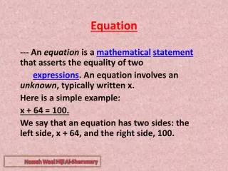
Energy Equation
730 likes | 878 Vues
Explore the expanded Bernoulli's equation for fluid flow, considering energy additions, extractions, and losses in the system. Learn about pump power requirements, velocity calculations, and fluid dynamics principles. Utilize the Venturi-meter to measure discharge accurately.

Energy Equation
E N D
Presentation Transcript
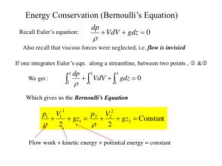
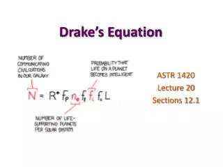
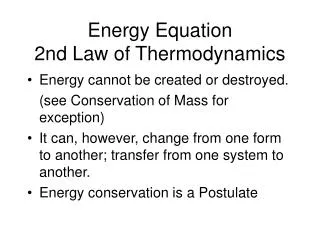
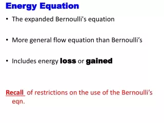
Energy Equation • The expanded Bernoulli's equation • More general flow equation than Bernoulli’s • Includes energy loss or gained Recall of restrictions on the use of the Bernoulli’s eqn.
Motor • hA = energy added by mechanical device ( pump) • hR = energy removed ( motor / turbine ) • hL = energy losses ( friction + minor losses) Valve Pump
The magnitude of friction, (head loss) is proportional to the velocity head • K = resistance coefficient found from Darcy-Weisbach equation Total Energy per unit weight (pts 1 and 2)
But Energy Equation So
Energy equation written in the direction of flow. • The Algebraic signs are very critical From above: • Pump adds energy • Frictional losses remove energy • motor extracts energy
1 Example Large reservoir 3.5 m 4.0 m 2 10 cm Find Q= 0.03m3/s
From point 1point 2 Both points are exposed to the atmosphere Reservoir large, so very large surface area. No mechanical devices Hence or
These losses are frictional (pipe friction) and minor (valves, elbows)
Pump power Requirements Mechanical Efficiency
Given the following T = 100c, Q = 115 l/min (1.92x 10⁻³ m3) PA= 700 kPa, PB = 125 kPa, hL = 4.0 m Calculate: PR, PO if Em = 0.85 Example A 1.8m B
Solution Solve for
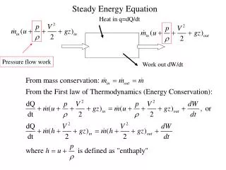
Applications of the Bernoulli's Equation 2 1 Note Streamlines move to the left and right Centre streamline, goes to the tip of the blunt body and stops. Velocity is zero - the fluid does not move at this point. Point (2) called stagnation point.
Pitot Tube Open s 1
Applying general Energy Equation (Bernoulli’s) between points 1 & S Now Hence
Static pressure = Static pressure head = velocity head Stagnation or total pressure Total pressure head Only the difference between the total pressure head and static pressure head gives velocity
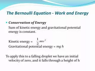
Venturi-Meter • Venturi-meter - device for measuring discharge • Consists of a rapidly converging section which increases velocity of flow and hence reduces the pressure. • It then returns to the original dimensions of pipe by a gently diverging (diffuser) section. • Measuring pressure differences between two points the discharge can be calculated. • Energy loss in the venturi-meter is very small.
About 6 About 20
Apply Bernoulli's equation along the streamline from point 1 to 2 Using continuity equation find velocity u2
Substituting this into and rearranging the Bernoulli's equation
Hence theoretical discharge Actual discharge, taking into account losses due to friction
Manometer Equation Express discharge in terms of the manometer readings Simplify Hence actual discharge is
Expression for discharge does not include any terms for elevation or orientation (z1 orz2)of the venturi-meter. Hence the meter can be at any convenient angle to function. The smoother the contraction, the lesser the head loss Typically
The purpose of the diffuser in a Venturi-meter: • To assure gradual and steady deceleration after the throat. • This design is to ensure pressure rises again to a value near the original value before the venturi-meter. • The angle of the diffuser is usually between 6 and 8 degrees. • If the angle is wider than this limit, the flow might separate from the walls resulting in increased friction, energy and pressure loss.
If the angle is less than this limit, the meter becomes very long and pressure losses again become significant. The efficiency of the diffuser of increasing pressure back to the original is rarely greater than 80%.
Example B 200mm 0.46 m A Unknown “y” 300mm 1.18 m Specific gravity = 1.29
Known parameters Consider Point A and B
Manometer equation Now we need , so divide by
1 Flow through a Small Orifice • Consider flow from a tank through a hole (orifice) in the side close to the base. • General arrangement of streamlines as above orifice h 2 Vena-contracta Datum
Shape of holes edges is sharp - Contact between hole and the fluid minimized. • Hence frictional losses decreased. • Streamlines contract after the orifice to a minimum value when they become parallel. • At this point, the velocity and pressure become uniform across the jet. • Convergence is called vena-contracta. (‘Latin 'contracted vein').
To calculate the flow, it is important to know the amount of contraction • Predict the velocity at the orifice using Bernoulli's equation. • Apply Bernoulli's equation to the streamline joining • point 1 on the surface of the reservoir to point 2 at the centre of the orifice.
Surface velocity negligible (u1=0) and the pressure atmospheric (p1= 0). • At the orifice, jet is open to the air so pressure is atmospheric (p2= 0). • Datum line through the center of the orifice, • z1= h and z2=0 theoretical velocity
Actual velocity • Actual area of the jet is area of the vena-contracta not the area of the orifice. • Area at vena-contracta obtained by using the coefficient of contraction for the orifice Cv - coefficient of velocity (0.97 - 0.99) Cc - coefficient of contraction
Discharge through the orifice Cd - coefficient of discharge
Determination of Coefficient of Velocity Three methods used: • By measurement of coordinates (Trajectory method) • By momentum method • By pitot-tube
By measurement of coordinates (Trajectory method) • Measure horizontal and vertical coordinates of the jet as it falls under gravity. • The jet contracts and forms the venacontracta at a distance of d/2 from plane of the orifice. H venacontracta x x y y
Let • u be the velocity at the venacontracta • x and y be the coordinates of a point on the jet after time t. • Applying the equation of motion
Eliminating t But • So Knowing x and y, and the head H, Coefficient of velocity is obtained
A circular orifice, 3.5 cm diameter is made in the vertical wall of a tank. The jet falls vertically through 0.5 m while moving horizontally through a distance of 1.5 m. Calculate the coefficient of velocity if the head causing flow is 1.2 m. If the discharge is 2.80 * 10^-3 m^3, calculate
In a small amount of time Volume Removed from tank The two are equal Solving for time
So Integrating from depth Time to drain a tank
Example What is the time taken to drain a tank from 3m to 0.5m.Tank diameter, D = 1.5m; nozzle diameter = 50mm. Take Cd = 0.92 Solution:
Time for a Tank to Empty Tank empty
Notches and Weirs Depending on the shape • Rectangular • Triangular • Trapezoidal Depending on the form of the crest • Sharp crested • Broad crested • Others
SHARP CRESTED WEIR BROAD CRESTED WEIR
General Notch Equation b h H h