Download
1 / 17
180 likes | 311 Vues
Axial compressors 1 + compEDU tutorial. Elementary axial compressor theory Velocity triangles Limitations for compressor performance relative Mach number limitations deflection limitation Degree of reaction compEDU Axial compressor tutorial Overhaul and maintenance lab specification.

E N D
Axial compressors 1 + compEDU tutorial Elementary axial compressor theory Velocity triangles Limitations for compressor performance relative Mach number limitations deflection limitation Degree of reaction compEDU Axial compressor tutorial Overhaul and maintenance lab specification
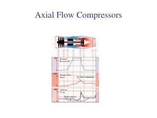
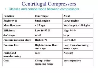
Axial flow compressors • Working fluid is accelerated by the rotor and decelerated by the stator • Boundary layer growth and separation (stall) limits the rate of allowable diffusion • Diffusion (decrease of velocity and increase of static pressure) occurs in stator and in relative frame of rotor
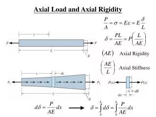
Elementary theory • Energy equation for control volumes (again): • Adiabatic compression process (work added to system - sign convention added work = -w) • Rotor => -(-w) = cp(T02-T01) <=> w = cp(T02-T01) • Stator => 0 = cp(T03-T02) => T03= T02
How is the temperature rise related to the blade angles ? • We study change of angular momentum at mid of blade (as approximation)
Theory 9.1 – Stage temperature rise • Relative and absolute refererence frames are related by: C = V + U • Many compressors have been designed assuming Ca=Ca1=Ca2. We will assume this for the following derivation • We repeat the derivation of theoretical work used for radial compressors and axial turbines:
Theory 9.1 – Stage temperature rise • Combining that flow occurs at a constant radius (=>U2=U1) and that the axial velocity is assumed to be constant (design assumption) we get:
Theory 9.1 – Stage temperature rise • Using the trigonometric relation from above together with the work relation we get: • Introducing the derived relation for work into the energy equation finally yields relationbetween air angles and temperaturerise:
Conclusions To obtain a high temperature rise we should: • High blade speed (U) • High axial speed (Ca) • High fluid deflection (β1- β2) Blade stresses and aerodynamic considerations limit these design selections • The isentropic efficiency then relates the blade angles to the pressure rise of the stage
Axial velocity and Mach numbers • Relative Mach number greatest at blade tip. Assuming axial and constant velocity over rotor entry: • The static temperature is: • Speed of sound is: • Typical (high) values : C=200 m/s, U = 450 m/s => Mrel,tip= 1.5 (check this yourself)
Fluid deflections and limitations • The relative velocity decreasesin the rotor. • Too rapid retardation => separation and excessive losses. • A design criteria to limit the retardation is set by the de Haller number: • High fluid deflection => high rate of diffusion.
Fluid deflections and limitations • A better estimate of diffusion can be derived if pitch and chord is taken into account. • Greatest diffusion from Vmax to V2 on suction side. Here, boundary layer growth will be most severe => largest part of losses created in this region • We approximate the diffusion, D, by this velocity change according to:
Blockage • Boundary layer growth at annulus walls creates a peaky flow profile • For a fixed design (α 1 and β 2) can no longer be varied within the diffusion constraints), increasing Ca leads to a decrease in work output: • This is approximated by the use an empirical factor - the work done factorλ according to:
Degree of reaction • Diffusion takes place in both rotor and stator. • The division characterizes the design • The quantity measuring this division is the degree of reaction - Λ : • We will derive Λ assuming: • variation in cp over temperature ranges is neglible => we can use temperatures • Ca constant • C3=C1 => Δ TStage= Δ T0,Stage
Degree of reaction • Let Δ TA and Δ TB denote the static temperature rise in the rotor and stator respectively. Then: • Use that all work input occurs in the rotor, i.e. • Combining the two relations yields:
Degree of reaction • From the definition of Λ we then have:
Degree of reaction Basic velocity triangles again: Thus, we get:
Know how to relate blade angles to stage temperature rise Understand how fluid mechanics limits the performance of axial compressor design: Mach number limitations Blockage Have a basic insight of gas turbine overhaul and maintenance as given by compEDU tutorial Learning goals